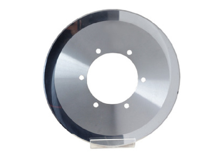
Tungsten carbide mining tools, with their unique properties, are widely used in oil drilling, coal mining, rocking drilling, geological prospecting and other industries. Its high temperature, wear and corrosion-resistant properties to meet specific conditions required for mining.
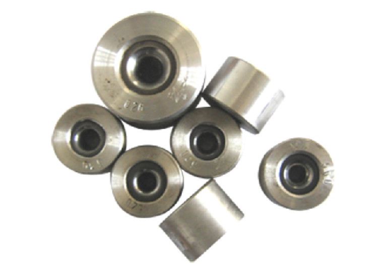
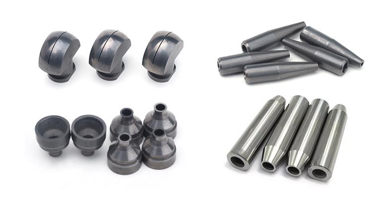
Tungsten Carbide Mining Tips
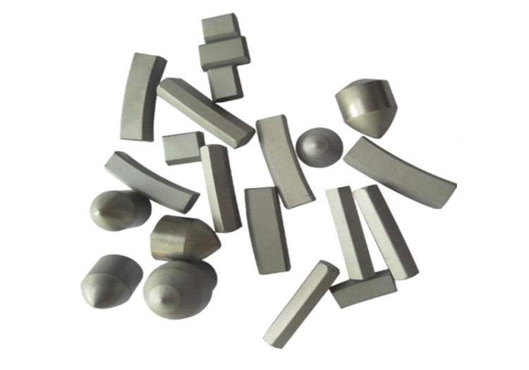
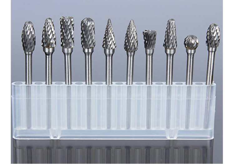
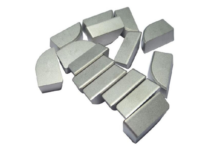
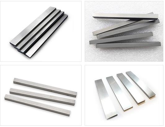
Tungsten carbide tips are widely used in oilfield drilling and snowplow, or other equipment because of their unique properties. Tungsten carbide milling tips mainly include tips for road milling, tips for coal mining, tips for tunneling and tips for trenching, etc. In a word, tungsten carbide mining tips are used for rock cutting and milling with big consumption. According to different oilfield drilling machinery, such as roller cone bit, DTH bit, geological drilling tool, carbide tips are divided into different standard styles: P-type, Z type, X type, etc. The material grades include YG4C, YG8, YG11C, YG15. YG8 material grades are used for coring crowns, electrical coal drill bits, coal cutting picks used in geological prospecting, coal mining. YG11C grades are used for heavy rock drills and rotary hammer rock drills cutting hard rocks. YG15 grade has a high intension, lower wear resistance, suitable for making bits for rotary machine and heavy rotary machine to drill hard and very hard rock.
All of the tungsten carbide mining tips provided by XYMJ are made from virgin raw materials. Various sizes and styles are available here and we can also make the tips in any new design and sizes to meet our customers’ requirements.
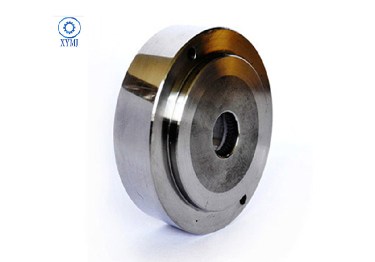
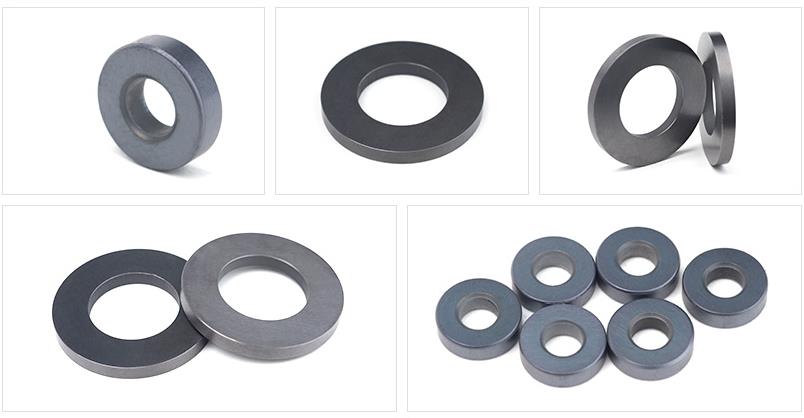
Tungsten Carbide Button
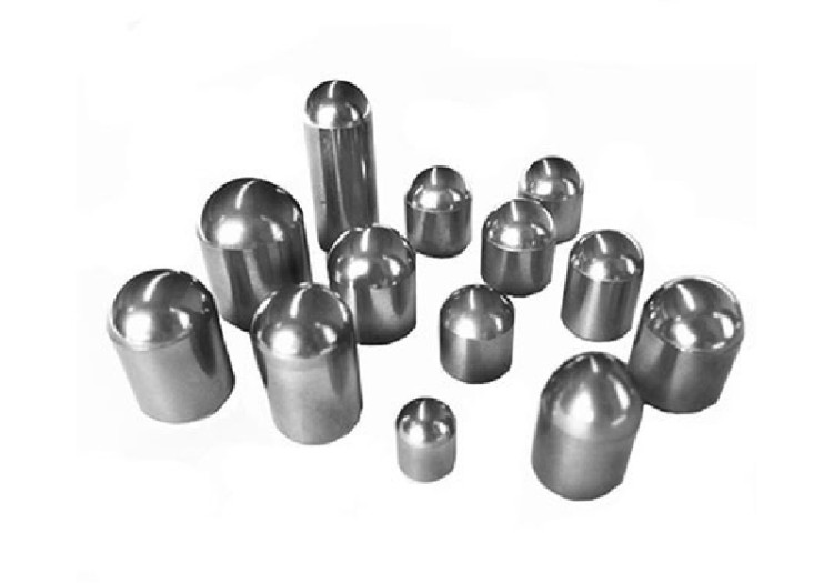
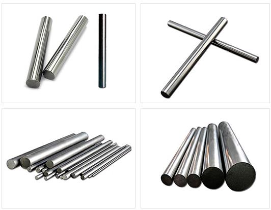
We have a variety of types of carbide buttons, such as spherical buttons, ballistic buttons, conical buttons, wedge buttons, wedge crested chisel, wingtip, spoon buttons, flat-top buttons, serrated buttons, sharp claw, auger tips, road digging buttons and so on.
The tungsten carbide button is widely used in petroleum drilling, snow plow equipment, cutting tools, mining machinery, road maintenance and coal drilling tools. It is also can be used as an excavating tool for Tunneling, quarrying, mining and construction. In addition, it can be applied as drill accessories for rock drilling machine and deep hole drilling tools. They have good impact toughness and excellent wear resistance.
Features
1.high strength and high hardness.
2.excellent hardness, wear-resistance, high elastic modulus, high flexural strength.
3.good chemical stability (acid, alkali, high temperature oxidation),impact resistance.
4. good toughness, low coefficient of expansion etc.