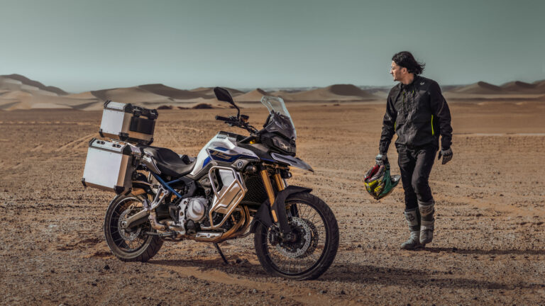
The adventure motorcycle segment in Europe has witnessed a surge in demand over the past few years, with riders increasingly seeking machines that can handle both off-road terrains and long-distance touring. Enter the VOGE DS900X, a standout motorcycle that promises to revolutionize the European adventure market with its perfect blend of power, reliability, and innovative features.
A Powerful Machine for the Adventurous Rider
At the heart of the VOGE DS900X lies a robust 900cc parallel-twin, liquid-cooled engine that offers a blend of performance and reliability, making it a perfect choice for the European adventure enthusiast. With over 90 horsepower and 85 Nm of torque, the DS900X ensures rapid acceleration and ample power, allowing riders to conquer both rugged off-road trails and the fast-paced highways of Europe. Whether it’s steep mountain passes, gravel roads, or smooth highways, the DS900X offers unrivaled performance that European riders demand.
The engine is paired with a 6-speed transmission that offers smooth gear transitions, while the slipper clutch ensures that the rear wheel remains stable during aggressive downshifting. This makes the DS900X an ideal motorcycle for riders who enjoy long-distance touring or tackling challenging trails across diverse European landscapes.
Engineered for Adventure: Design and Durability
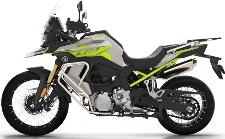
The VOGE DS900X isn’t just about power; it’s built to endure tough conditions. The motorcycle features a high-strength steel frame combined with an aluminum swingarm for durability and weight reduction. This structure allows the bike to handle the bumps and stresses of off-road riding while still providing a comfortable, stable ride on tarmac.
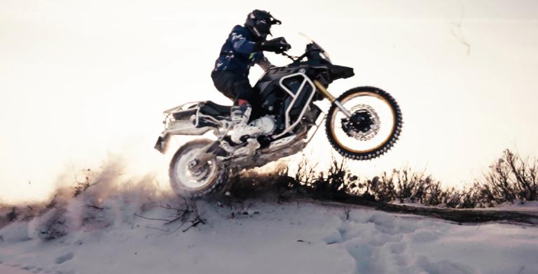
Its long-travel suspension system, equipped with adjustable front forks and a rear monoshock, absorbs even the most challenging terrain with ease. The 21-inch front and 17-inch rear wheels, fitted with off-road tires, ensure that the DS900X delivers optimal traction and stability on rough trails. Riders can confidently navigate through the mud, sand, or rocky terrain that is characteristic of Europe’s diverse adventure riding destinations.
Comfort and Control for Long-Distance Touring
Comfort is paramount for any long-distance adventure, and the VOGE DS900X delivers. The ergonomically designed seat is built for comfort on long rides, with plenty of padding and support for riders. Its low seat height of 830mm provides easy access for a wide range of riders, ensuring both comfort and control when riding for extended periods.
The handlebars are also designed to provide an upright riding position, reducing strain on the rider’s back and wrists, making the bike suitable for long-haul touring. European adventure riders will find that the DS900X offers a relaxed yet responsive riding position, perfect for hours of exploration.

Safety Features for the European Road
Safety is always a top priority, especially when venturing into challenging terrain or navigating busy European streets. The VOGE DS900X comes equipped with dual-channel ABS, which enhances braking performance in wet or slippery conditions. This ensures that riders have maximum control and safety whether they’re crossing slick mountain roads or riding through rain-soaked highways.
Additionally, the traction control system (TCS) optimizes the bike’s performance on various surfaces, preventing wheel slip when accelerating on loose gravel or slippery roads. With these advanced features, the DS900X ensures riders can take on a wide variety of terrains with confidence.
Digital Features for the Connected Rider
Modern-day adventure riders demand more from their motorcycles than just power and handling—they want connectivity and modern features to make their journeys more enjoyable. The VOGE DS900X is equipped with a 7-inch full-color TFT display that provides real-time information on speed, fuel level, gear position, tire pressure, and more. This allows riders to monitor their performance and plan their trips efficiently.
Bluetooth connectivity is another standout feature, allowing riders to pair their smartphones for hands-free calls, music streaming, or navigation. Whether you’re following a route across the Alps or finding the best dirt trails in Spain, the DS900X keeps you connected and in control.
A Growing Presence in Europe
As the European motorcycle market continues to evolve, the demand for versatile adventure motorcycles that can handle both the open road and off-road challenges has never been higher. The VOGE DS900X positions itself as a strong contender in the European adventure motorcycle market, offering exceptional value, performance, and durability.
With its strong engine, robust design, comfort-focused features, and advanced technology, the DS900X is poised to capture the attention of adventure enthusiasts who want a motorcycle capable of handling Europe’s diverse terrain. From the sun-drenched Mediterranean roads to the rugged mountain passes of the Alps, the DS900X is the ultimate companion for any adventure.
Summary
The VOGE DS900X ADV motorcycle is a statement of adventure, power, and freedom. Its impressive features, combined with its rugged design and modern technologies, make it a standout in the competitive European adventure motorcycle market. For those who crave the thrill of exploration, the VOGE DS900X offers everything a rider needs to enjoy the journey, whether it’s traversing challenging landscapes or cruising through scenic highways.