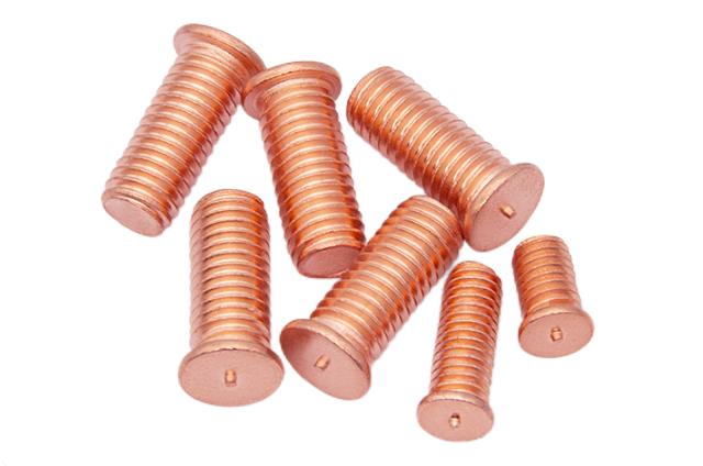
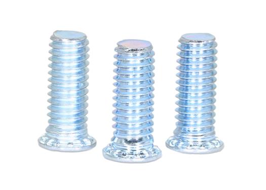
When it comes to repairs or remodeling, whether in automotive, mechanical, or construction applications, removing a stud safely is often a necessary but challenging task. A stud, which is essentially a bolt or rod embedded in a surface, can become stripped, rusted, broken, or otherwise stuck. Removing it without causing damage to the surrounding materials or threads is crucial to ensuring a clean and professional result. The key to successful stud removal lies in preparation, technique, and patience.
The Importance of Preparation
Before taking any action, it’s essential to assess the situation carefully. Determining the material the stud is embedded in, its condition, and the surrounding environment will guide your choice of tools and method. For example, a corroded metal stud in an engine block will require a different approach than a threaded rod embedded in wood or drywall. Equally important is understanding whether the stud is flush with the surface, protruding, or broken off inside the hole.
Once the assessment is complete, the first step in almost every case is to apply a penetrating oil. Letting a quality lubricant soak into the threads for at least 10 to 15 minutes can make the difference between a smooth extraction and a nightmare of stripped threads and damaged parts. This step reduces friction and helps to loosen any corrosion or debris binding the stud.
Mechanical Methods for Removal
When the stud is intact and has enough of a protrusion to grab onto, the simplest method involves using locking pliers or a stud extractor tool. Firm, even pressure is necessary—too much force can shear the stud, while too little will allow the tool to slip and damage the stud’s surface. If the stud doesn’t budge, carefully applying heat to the surrounding area (especially in metal-on-metal scenarios) can help by expanding the outer material and freeing the threads.
For studs that are broken off flush or below the surface, more precision is required. A center punch helps create an accurate starting point for drilling. Begin with a small drill bit to create a pilot hole directly in the center of the broken stud. This pilot hole will then guide a larger bit or an extraction tool, such as a screw or bolt extractor. The extractor is gently twisted into the hole in the reverse direction, and with slow, even torque, the stud can usually be backed out cleanly.
Avoiding Damage and Future Problems
One of the biggest risks in stud removal is damaging the internal threads of the component. Using the right size drill bit and extractor is essential. If the threads become damaged during removal, a thread repair kit or a helicoil insert may be needed to restore the original integrity. It’s also advisable to clean the threads with a tap once the stud is removed, ensuring a smooth surface for the replacement fastener.
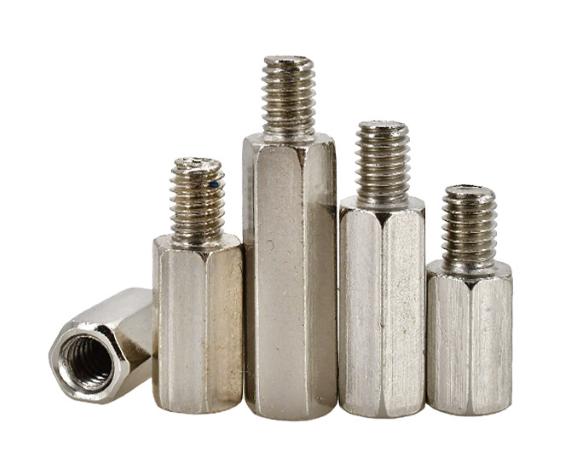
In construction settings, such as when removing hexagon studs from walls, care must be taken not to compromise the structural integrity of the surrounding frame. This might involve cutting the stud carefully and pulling it out in sections, rather than yanking or prying with force.
The Role of Patience and Precision
Perhaps the most underrated tools in stud removal are patience and precision. Rushing the job increases the likelihood of breaking tools, damaging materials, or injuring yourself. Taking the time to prepare properly, using the correct tools, and working slowly and deliberately will often yield better, safer results.
In the end, removing a stud safely isn’t just about muscle—it’s about method. Whether in a mechanic’s garage, a laboratory, or a renovation project, the process calls for the right blend of strategy and skill to ensure success without compromise.