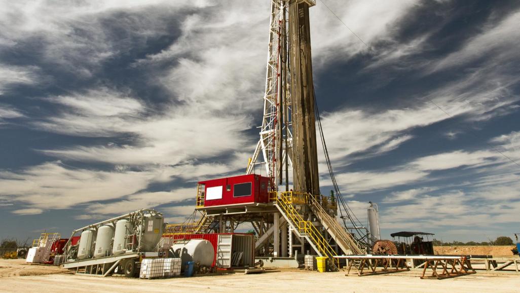
Land oil rig installation is a critical phase in onshore drilling operations. It involves a complex interplay of logistics, engineering, and safety procedures to ensure the rig is correctly assembled and fully operational. As the oil and gas industry continues to embrace digital transformation, simulation technology has emerged as a powerful tool to streamline rig installation processes, minimize risk, and improve workforce readiness.
Key Steps in Land Oil Rig Installation
Site Preparation
The process begins with site selection, followed by clearing, leveling, and the construction of access roads and foundations to support the heavy weight of drilling equipment.
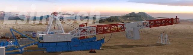
Transportation and Assembly of Rig Components
Rig modules—including the derrick, substructure, mud system, and power units—are transported in parts and assembled onsite using cranes and support vehicles.
Infrastructure Setup
Water, power, fuel supply systems, and data communications are installed to support rig operations.
Drilling System Integration
The rotary table, top drive, mud pumps, blowout preventer (BOP), and control systems are installed and tested.
Safety and Compliance Checks
Before commissioning, the rig undergoes rigorous safety inspections, function tests, and regulatory reviews.
The Use of Simulation Technology in Land Oil Rig Installation
As land-based rig setups become more sophisticated, the margin for error shrinks. Oil and gas simulation technology addresses these challenges through several key applications:
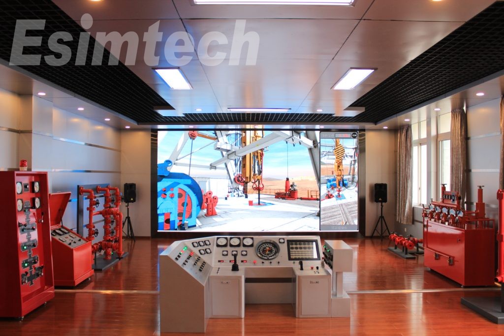
1. Pre-Installation Planning and Virtual Testing
Engineers use 3D simulation models to virtually construct the rig before physical installation.
These digital replicas allow planners to optimize rig layout, identify potential conflicts, and streamline logistics.
Virtual rig-up simulations reduce guesswork and cut installation time.
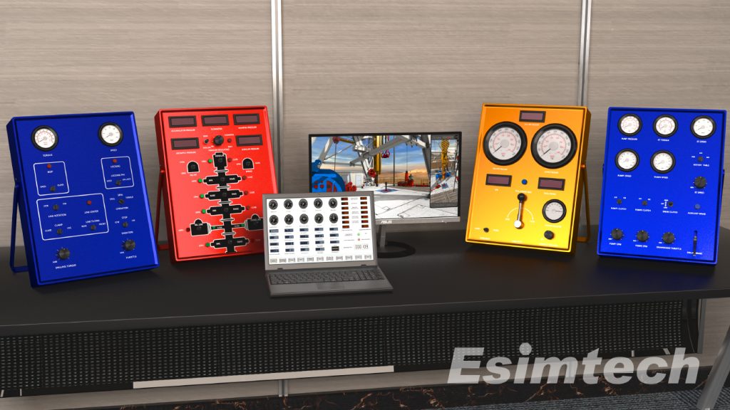
2. Training of Installation Crews
Simulation-based training platforms help prepare crews for real-world rig assembly.
Trainees interact with immersive environments that mimic rig components, handling procedures, and emergency scenarios.
This approach significantly reduces the learning curve while promoting a culture of safety.
3. Safety Risk Assessment
Land rig installation simulators model various failure scenarios such as equipment malfunctions, structural instability, or human errors.
Teams can practice mitigation strategies in a risk-free environment, improving decision-making under pressure.
4. Logistics and Equipment Handling Optimization
Simulation tools help analyze crane reach, load paths, and truck access to prevent bottlenecks.
Efficient sequencing of component delivery and assembly minimizes downtime.
5. Real-Time Monitoring and Feedback Integration
Some advanced simulations integrate real-time sensor data from the site to adjust the model as the installation progresses.
This creates a dynamic feedback loop for informed decision-making during rig-up.

Benefits of Simulation Technology
Reduced Installation Time: Streamlining tasks through virtual rehearsal lowers the duration of rig setup.
Improved Safety: Fewer incidents due to better crew preparation and hazard anticipation.
Cost Efficiency: Less rework and fewer delays mean lower installation costs.
Enhanced Communication: Visual simulations aid cross-functional coordination among teams and contractors.
Summary
Land oil rig installation is no longer solely a matter of manpower and heavy machinery—it is increasingly becoming a digital process. Simulation technology offers a powerful edge by enabling thorough planning, hands-on training, and real-time decision support. As the industry strives for safer, faster, and more cost-effective operations, embracing simulation in rig installation is proving to be a critical component of success.


 </p
</p