Tension control plays a crucial role in numerous industrial applications, especially in processes where materials experience rapid speed changes. These applications include printing, web handling, textile manufacturing, and metal processing. Ensuring precise tension control under rapid speed change conditions is essential to maintain product quality, prevent material damage, and enhance operational efficiency.
Challenges of Tension Control in High-Speed Applications
Applications involving rapid speed changes pose significant challenges for maintaining consistent tension. These challenges include:
Inertia Effects: Sudden acceleration or deceleration can cause tension fluctuations due to the inertia of moving rolls or materials.
Material Properties: Different materials, such as films, foils, and textiles, have varying elasticity and stretchability, making tension stability difficult to achieve.
Control System Delays: Traditional tension control systems may struggle with response times, leading to overshoot or lag in adjustments.
Friction Variability: Changes in friction at guide rolls, rollers, or drive systems can result in inconsistent tension levels.
Key Strategies for Effective Tension Control
To address these challenges, advanced tension control techniques and system optimizations are required.
1. Closed-Loop Tension Control Systems
Utilizing closed-loop tension control mechanisms with feedback sensors ensures continuous monitoring and real-time adjustments. Load cells, ultrasonic sensors, and dancer systems can help maintain optimal tension levels even during sudden speed variations.
2. Adaptive Control Algorithms
Advanced tension control systems employ adaptive control algorithms that can predict and adjust tension variations proactively. These systems utilize machine learning or model predictive control (MPC) to optimize performance dynamically.
3. High-Precision Dancer Rollers
Dancer rollers with servo-driven actuators provide immediate tension compensation. They act as buffers, absorbing sudden changes in material speed and reducing the risk of tension fluctuations.
4. Intelligent Drive Systems
Variable frequency drives (VFDs) and servo motors integrated with advanced control software can adjust motor torque and speed precisely to maintain tension stability.
5. Taper Tension Control for Winding Applications
In applications such as roll-to-roll processing, taper tension control adjusts tension levels based on roll diameter changes, preventing excessive stress on materials.
6. Integration of Edge and Web Guide Systems
Ensuring proper alignment using web guide systems reduces lateral tension inconsistencies, preventing material wrinkles or misalignment.
Benefits of Advanced Tension Control in Rapid Speed Changes
Implementing effective tension control solutions in high-speed applications offers several advantages:
Enhanced Product Quality: Consistent tension prevents defects such as stretching, tearing, or misalignment.
Reduced Material Waste: Stable tension reduces the likelihood of material breakage, improving efficiency.
Higher Production Speeds: Optimized control enables faster processing without compromising quality.
Extended Equipment Lifespan: Minimizing mechanical stress on rollers and drives prolongs component durability.
Conclusion
Effective tension control in applications with rapid speed changes requires a combination of advanced control systems, precision sensors, and intelligent drive technologies. By implementing adaptive control strategies, industries can achieve improved efficiency, reduced material waste, and enhanced product quality, ensuring optimal performance in high-speed manufacturing environments.
Sample preparation is a critical step in Inductively Coupled Plasma Mass Spectrometry (ICP-MS), ensuring accurate, precise, and reproducible results. Proper preparation allows for effective detection of trace elements by transforming samples into a form that can be introduced into the instrument. This process involves converting solid or complex matrices into a homogeneous solution while minimizing contamination and interference.
Sample Types and Their Preparation Methods
The first step in sample preparation involves understanding the sample type. Aqueous samples, such as water or liquid-based solutions, generally require minimal preparation. These samples are typically filtered to remove particulates and acidified with ultrapure nitric acid to maintain sample stability and prevent metal precipitation. Acidification also helps suppress microbial activity, which could otherwise alter the sample’s composition.
For solid samples, including metals, biological materials, and environmental matrices like soils, the process is more complex. One of the most common methods for solid sample preparation is acid digestion. This involves dissolving the sample in a strong acid or a combination of acids to break down the material into its elemental components. Open-vessel digestion, often performed on a hotplate, is suitable for less complex materials. However, for more resistant matrices like geological samples, microwave digestion is preferred. This method uses microwave energy to accelerate the digestion process under controlled pressure and temperature conditions, offering faster and more complete dissolution.
In cases where acids alone cannot fully break down the sample, fusion techniques are employed. Fusion involves mixing the sample with a flux, such as lithium metaborate, and heating it to form a molten mixture. This solidifies into a glass-like matrix that can be dissolved in dilute acids. This method is particularly useful for refractory materials that resist conventional acid digestion.
Key Considerations in Sample Preparation
Another key aspect of sample preparation is controlling contamination. Since ICP-MS can detect elements at extremely low concentrations (parts per trillion), even minor contamination from laboratory environments or reagents can skew results. Using ultrapure reagents, acid-washed labware, and working within a clean, controlled environment is essential. Furthermore, implementing reagent blanks—samples containing only the acids used—helps identify and correct for any background contamination.
Matrix effects are also a major consideration during sample preparation. The composition of the sample matrix can interfere with ionization efficiency or cause signal suppression. To address this, laboratories often dilute samples to reduce matrix concentration or employ matrix matching, where calibration standards are prepared in a similar chemical environment as the sample. Using internal standards—elements not present in the sample but added in known amounts—helps correct for variations in sample introduction and instrumental drift.
Quality Control Measures
Quality assurance is embedded throughout the preparation process. This involves using certified reference materials (CRMs) to validate accuracy, performing replicate analyses to assess precision, and conducting spike recovery tests to evaluate the method’s efficiency. Regularly analyzing blanks ensures that contamination is monitored, and maintaining strict protocols enhances the reproducibility of results.
Advances in Sample Preparation Techniques
Advancements in automation have streamlined sample preparation for ICP-MS. Automated microwave digestion systems and autosamplers reduce manual handling, improving efficiency and minimizing the potential for human error. Additionally, innovations like direct solid sampling methods are emerging, which bypass the need for extensive chemical preparation, offering quicker analysis for specific applications.
In conclusion, effective sample preparation in ICP-MS is fundamental for achieving reliable analytical results. Whether dealing with simple aqueous solutions or complex solid matrices, careful handling, thorough digestion, and rigorous quality control are essential. By optimizing preparation techniques and minimizing sources of error, laboratories can leverage the full capabilities of ICP-MS for precise trace element analysis.
The oil and gas industry has long been a cornerstone of global energy production, but it is also a significant contributor to greenhouse gas emissions, particularly carbon dioxide (CO₂). As the world transitions toward a low-carbon future, Carbon Capture and Storage (CCS) has emerged as a critical technology to reduce emissions while maintaining energy security. CCS is especially relevant in oil and gas drilling, where it can mitigate the environmental impact of fossil fuel extraction and processing. This article explores how CCS is applied in the oil and gas industry, its benefits, challenges, and its role in shaping a more sustainable energy future.
What is Carbon Capture and Storage (CCS)?
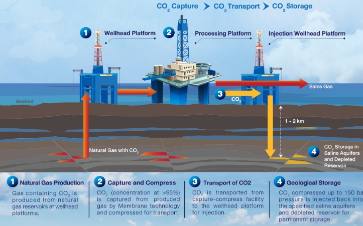
Carbon Capture and Storage (CCS) is a process that captures CO₂ emissions from industrial sources, transports them to a storage site, and securely stores them underground to prevent their release into the atmosphere. The process involves three main steps:
Capture: CO₂ is separated from other gases produced during industrial processes, such as power generation or oil and gas drilling.
Transport: The captured CO₂ is compressed and transported via pipelines, ships, or trucks to a storage site.
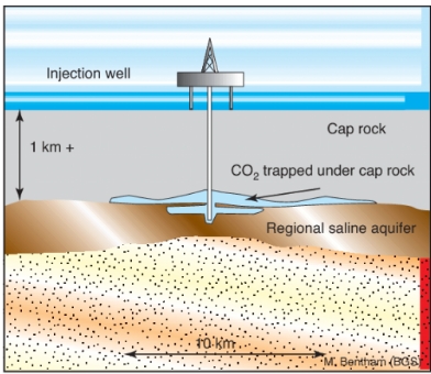
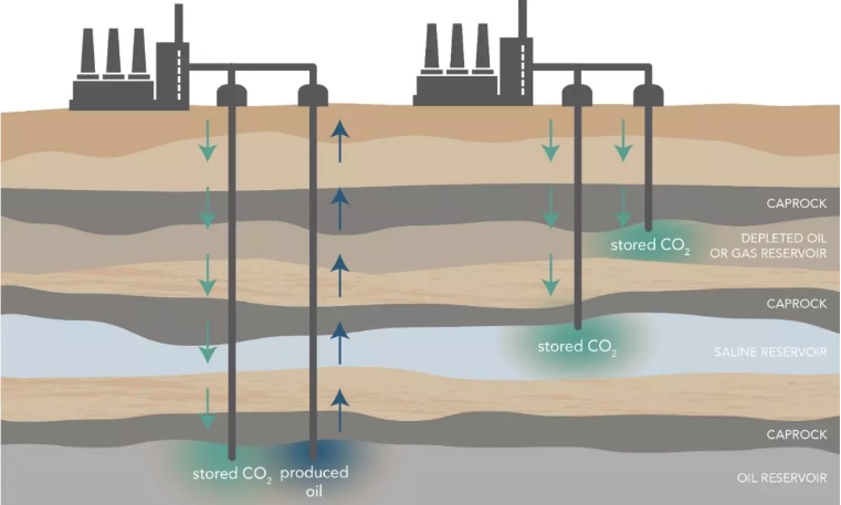
Storage: The CO₂ is injected deep underground into geological formations, such as depleted oil and gas reservoirs or saline aquifers, where it is permanently stored.
How CCS is Applied in Oil and Gas Drilling
The oil and gas industry is uniquely positioned to leverage CCS technology due to its expertise in subsurface operations and existing infrastructure. Here’s how CCS is applied in this sector:
1. Enhanced Oil Recovery (EOR)
One of the most common applications of CCS in the oil and gas industry is Enhanced Oil Recovery(EOR). In this process, captured CO₂ is injected into depleted oil reservoirs to increase pressure and improve oil extraction. The CO₂ mixes with the oil, making it less viscous and easier to pump to the surface. This not only boosts oil production but also stores CO₂ underground, reducing emissions.
Example: The Petra Nova project in Texas, USA, captures CO₂ from a coal-fired power plant and uses it for EOR in an oil field.
2. Capturing Emissions from Upstream Operations
Oil and gas drilling operations release CO₂ during processes like flaring, venting, and fuel combustion. CCS can capture these emissions directly at the source, preventing them from entering the atmosphere.
Example: The Sleipner project in Norway captures CO₂ from natural gas production and stores it in a saline aquifer beneath the North Sea.
3. Decarbonizing Natural Gas Processing
Natural gas processing often involves separating CO₂ from raw natural gas to meet pipeline specifications. Instead of releasing the separated CO₂, CCS can capture and store it.
Example: The Gorgon CCS project in Australia captures CO₂ from natural gas production and injects it into a deep saline formation.
4. Reducing Emissions from Refineries
Oil refineries are significant sources of CO₂ emissions due to energy-intensive processes like cracking and reforming. CCS can be integrated into refineries to capture and store these emissions.
Example: The Quest CCS project in Canada captures CO₂ from a hydrogen production unit at an oil sands refinery and stores it underground.
Benefits of CCS in Oil and Gas Drilling
1. Reduced Greenhouse Gas Emissions
CCS significantly reduces CO₂ emissions from oil and gas operations, helping the industry meet climate targets and regulatory requirements.
2. Enhanced Energy Security
By enabling the continued use of fossil fuels with lower emissions, CCS supports energy security during the transition to renewable energy sources.
3. Economic Opportunities
CCS creates new revenue streams, such as selling captured CO₂ for EOR, and supports job creation in engineering, construction, and operations.
4. Extended Life of Oil and Gas Assets
CCS allows oil and gas companies to extend the life of existing assets while reducing their environmental impact, providing a bridge to a low-carbon future.
5. Improved Public Perception
Adopting CCS demonstrates a commitment to sustainability, enhancing the industry’s reputation and social license to operate.
Challenges of Implementing CCS in Oil and Gas Drilling
1. High Costs
CCS is capital-intensive, requiring significant investment in capture technology, transportation infrastructure, and storage facilities.
2. Regulatory and Policy Barriers
Inconsistent regulations and lack of financial incentives (e.g., carbon pricing) can hinder CCS deployment.
3. Technical Risks
Ensuring the long-term stability and safety of CO₂ storage requires advanced monitoring and risk management.
4. Public Acceptance
Concerns about the safety and environmental impact of CO₂ storage can lead to opposition from local communities.
5. Infrastructure Limitations
Developing pipelines and storage sites requires significant time and resources, particularly in remote or offshore locations.
The Future of CCS in Oil and Gas Drilling
As the world strives to achieve net-zero emissions, CCS is expected to play a pivotal role in decarbonizing the oil and gas industry. Key trends and developments include:
1. Technological Advancements
Innovations in capture technology, such as solvent-based systems and membrane separation, are reducing costs and improving efficiency.
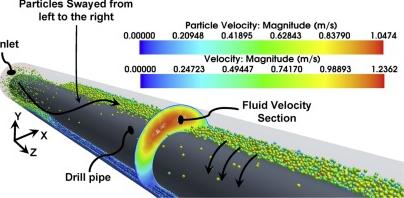
Simulation technologies used in oil and gas drilling, can model complex subsurface environments to predict CO₂ behavior, assess reservoir capacity, and evaluate potential leakage risks. By simulating injection processes and monitoring long-term storage performance, these technologies enhance the safety and efficiency of CCS operations. Key methods include reservoir simulation, geomechanical modeling, and fluid flow analysis, enabling accurate forecasting and improved decision-making throughout the CCS lifecycle.
2. Policy Support
Governments are increasingly recognizing the importance of CCS and introducing policies like tax credits, grants, and carbon pricing to incentivize adoption.
3. Collaborative Projects
Public-private partnerships and international collaborations are driving large-scale CCS projects, such as the Northern Lights initiative in Europe.
4. Integration with Renewable Energy
CCS can complement renewable energy by providing a reliable backup during periods of low wind or solar generation.
5. Carbon Utilization
Beyond storage, captured CO₂ can be used to produce synthetic fuels, chemicals, and building materials, creating new economic opportunities.
Conclusion
Carbon Capture and Storage (CCS) is a game-changing technology for the oil and gas industry, offering a practical solution to reduce emissions while maintaining energy production. By integrating CCS into drilling operations, the industry can significantly lower its carbon footprint, enhance energy security, and contribute to global climate goals. Although challenges remain, advancements in technology, policy support, and collaborative efforts are paving the way for widespread CCS adoption.
Wellbore integrity is a crucial aspect of oil and gas drilling, ensuring that a well remains structurally sound and leak-free throughout its operational life. Maintaining integrity is essential for preventing environmental contamination, equipment failures, and costly well interventions. Given the extreme conditions within the subsurface, a wellbore must be designed, constructed, and monitored using advanced engineering techniques and reliable materials.
Key Factors Affecting Wellbore Integrity
1. Proper Casing and Cementing
One of the key elements in ensuring wellbore integrity is proper casing and cementing. The casing provides structural support and prevents the well from collapsing, while cement seals off different geological formations to prevent unwanted fluid migration. A high-quality cementing job is essential for zonal isolation, ensuring that hydrocarbons flow only through designated pathways. If cement bonding is inadequate, gases or liquids can leak into surrounding formations or reach the surface, posing serious safety and environmental risks.
2. Drilling Fluid Management
Drilling fluids also play a significant role in wellbore stability. The correct mud weight must be carefully selected to maintain pressure balance within the formation. If the mud weight is too low, the wellbore can collapse, whereas excessive pressure can lead to formation fracturing and lost circulation. Additionally, drilling fluids help transport cuttings to the surface, cool the drill bit, and prevent differential sticking, all of which contribute to a stable wellbore environment.
3.Monitoring and Inspection Techniques
Real-time monitoring and inspection techniques are vital in detecting potential integrity issues before they escalate. Modern wellbore integrity assessments rely on tools such as acoustic, ultrasonic, and resistivity logs to evaluate casing and cement conditions. Pressure testing helps confirm the well’s ability to withstand operational stresses, while advanced downhole sensors provide continuous data on temperature, pressure, and fluid movements. By leveraging artificial intelligence and machine learning, operators can analyze these data streams to predict and prevent potential failures.
Challenges in Maintaining Wellbore Integrity
Challenges to wellbore integrity include corrosion, mechanical failures, and extreme temperature fluctuations. Corrosion, caused by exposure to aggressive formation fluids, can weaken casing materials over time. Mechanical issues, such as casing deformation due to high pressure, may compromise well stability. In deep wells, the effects of high temperatures and pressure cycles can induce material fatigue, increasing the risk of integrity failures.
Future Solutions and Innovations
To address these challenges, the industry continues to develop innovative solutions. The use of corrosion-resistant alloys in casing materials enhances durability, while advanced cement formulations incorporating nanoparticles improve sealing properties. The adoption of smart well technologies, including automated monitoring systems and predictive analytics, helps operators take proactive measures to maintain wellbore integrity.
Simulation Technologies for Ensuring Wellbore Integrity
Oil and Gas simulation technologies provide predictive modeling, real-time analysis, and risk assessment throughout the well’s lifecycle. Advanced software solutions, such as finite element analysis (FEA) and computational fluid dynamics (CFD), help engineers evaluate casing strength, cement bonding, and pressure distribution under extreme conditions. Geomechanical simulations predict formation stability, while AI-driven digital twins replicate real-time well conditions for proactive decision-making. These technologies enhance well design, optimize drilling parameters, and reduce failure risks, ensuring safe and efficient oil and gas operations.
Ensuring wellbore integrity is a fundamental priority for safe and efficient drilling operations. By implementing robust engineering practices, utilizing advanced monitoring technologies, and continuously innovating, the industry can enhance well reliability while minimizing risks. Investing in these strategies ensures long-term sustainability and safety in oil and gas exploration and production.
Custom teddy bears are becoming a creative and engaging tool in educational settings. These personalized plush toys serve more than just a decorative purpose—they can foster emotional connection, enhance learning experiences, and provide students with a sense of comfort and belonging. Whether used for reward systems, educational programs, or emotional support, custom teddy bears are a valuable asset in both traditional and non-traditional learning environments.
Enhancing Emotional Support and Well-Being
One of the most significant benefits of custom teddy bears in education is their ability to provide emotional support. For younger children, a teddy bear can offer a sense of security in unfamiliar or stressful environments such as a new classroom or during difficult transitions. Customizing these bears with school logos or motivational messages reinforces a connection to the educational institution and helps create a positive association with learning spaces.
Additionally, schools can use custom teddy bears as part of programs aimed at mental health and emotional well-being. For example, “comfort bears” are given to students experiencing anxiety or trauma, offering a tangible source of comfort. This approach has been especially effective in early childhood education and special education programs where emotional regulation is a key focus.
Incorporating Custom Teddy Bears into Learning Activities
Educators are finding innovative ways to use custom teddy bears to enhance curriculum delivery. For younger students, these toys can be used as storytelling companions—teachers can create custom bears to represent characters from books or historical figures, bringing stories to life and engaging students’ imaginations. Additionally, using themed teddy bears for science, geography, or math helps make abstract concepts more tangible and easier to understand.
Classroom-based initiatives such as “traveling teddy bears” encourage students to take the bear home and document its adventures through writing or drawing. This interactive activity supports literacy development while fostering a sense of responsibility. Custom teddy bears can also be used for language learning, where each bear is associated with specific vocabulary or phrases to reinforce lessons in a playful and memorable way.
Reward and Recognition Programs
Custom teddy bears make excellent rewards for academic achievements, attendance milestones, or positive behavior. Schools and educational organizations can design bears with personalized messages like “Star Reader,” “Perfect Attendance,” or “Kindness Champion.” This tangible form of recognition not only motivates students to excel but also serves as a lasting reminder of their accomplishments.
Moreover, these teddy bears can play a key role in graduation ceremonies for preschool or kindergarten students. Customized bears wearing miniature caps and gowns commemorate the occasion and provide children with a cherished memento of their educational journey.
Building School Spirit and Community
Custom teddy bears are also powerful tools for fostering a sense of community within schools. Institutions can create bears featuring their mascots or school colors to promote school pride. These bears can be sold as part of fundraising efforts or given as gifts during special events like open houses or student orientation.
For special education programs, custom bears can be tailored to represent inclusivity and diversity, helping students feel seen and valued. Such initiatives encourage empathy, cooperation, and an appreciation for differences among classmates.
Summary
Custom teddy bears offer more than just a cuddly companion—they are valuable educational tools that support emotional well-being, enhance learning experiences, and reinforce positive behavior. Whether used as a teaching aid, a reward for achievement, or a symbol of school pride, these personalized toys contribute to a nurturing and engaging educational environment. As schools continue to explore new ways to connect with students, custom teddy bears remain a timeless and meaningful resource for education.
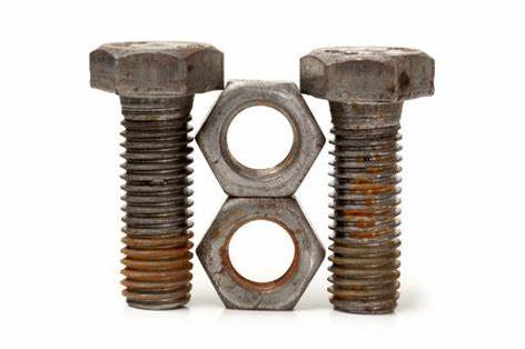
Rusted bolts can be a frustrating obstacle in construction, automotive repairs, and DIY projects. Over time, exposure to moisture, air, and corrosive elements can cause bolts to seize, making them difficult to remove. However, with the right techniques and tools, removing rusted bolts can be done safely and efficiently.
1. Understanding Why Bolts Rust and Seize
Bolts rust due to oxidation when exposed to moisture and oxygen. Factors that accelerate rusting include:
Humidity and rain exposure – Common in outdoor and marine applications.
Chemical exposure – Corrosive substances, such as road salt or industrial chemicals, speed up rusting.
Lack of lubrication – Dry fasteners are more prone to seizing over time.
Key Methods for Removing Rusted Bolts
1. Applying Penetrating Oil
Step 1: Spray a penetrating oil (such as WD-40, PB Blaster, or Liquid Wrench) around the rusted bolt.
Step 2: Allow the oil to soak for at least 15–30 minutes, or longer for heavily rusted bolts.
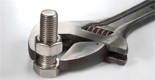
Step 3: Use a wrench or socket to attempt loosening the bolt.
Tip: Gently tapping the bolt with a hammer can help the oil penetrate deeper.
2. Using Heat to Expand the Metal
Step 1: Use a propane torch or heat gun to apply heat to the rusted bolt for 30–60 seconds.
Step 2: Allow it to cool slightly, then try loosening it with a wrench.
Caution: Avoid using heat near flammable materials or in enclosed spaces.
3. Breaking the Rust with a Hammer
Step 1: Place a wrench or socket on the bolt.
Step 2: Tap the head of the bolt with a hammer to break the rust bonds.
Step 3: Apply steady force to loosen the bolt.
4. Using a Bolt Extractor
For stripped or severely rusted bolts:
Step 1: Attach a bolt extractor socket to the bolt head.
Step 2: Use a breaker bar or impact wrench to apply force.
Step 3: Slowly turn counterclockwise to remove the bolt.
5. Cutting Off the Bolt (Last Resort)
If the bolt is beyond removal:
Step 1: Use a hacksaw, angle grinder, or reciprocating saw to cut through the bolt.
Step 2: Drill out the remaining part if necessary.
Regularly inspect and maintain fasteners to prevent excessive rust buildup.
In summary, removing rusted bolts requires patience and the right techniques. Penetrating oil, heat, and mechanical force are effective first-line methods, while bolt extractors and cutting tools serve as last-resort solutions. By taking preventive measures, you can avoid rust issues in future projects, ensuring smoother maintenance and repairs.
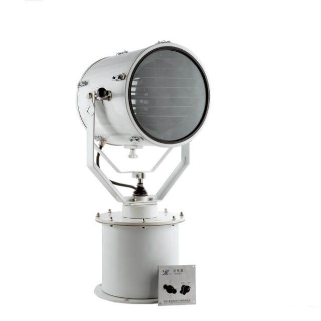
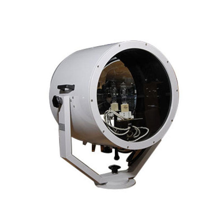
Marine searchlights are indispensable tools for ensuring safety, navigation, and operational efficiency on the water. Whether you’re operating a commercial vessel, a recreational boat, or a specialized maritime craft, having a reliable searchlight is crucial for visibility in low-light conditions, adverse weather, or emergency situations. However, with a wide variety of options available, purchasing the right marine searchlight can be a daunting task. This article provides a detailed guide to help you efficiently navigate the process of buying a marine searchlight, ensuring you make an informed decision that meets your specific needs.
Understanding Your Needs
The first step in efficiently buying a marine searchlight is to clearly understand your requirements. The type of vessel you operate, the primary purpose of the searchlight, and the operating environment are all critical factors to consider. For instance, a large commercial ship may require a high-powered, durable searchlight capable of withstanding harsh marine conditions, while a small recreational boat might benefit from a more compact and energy-efficient model. Identifying the primary use of the searchlight—whether for navigation, docking, search and rescue, or security—will also help narrow down your options.
Key Features to Prioritize
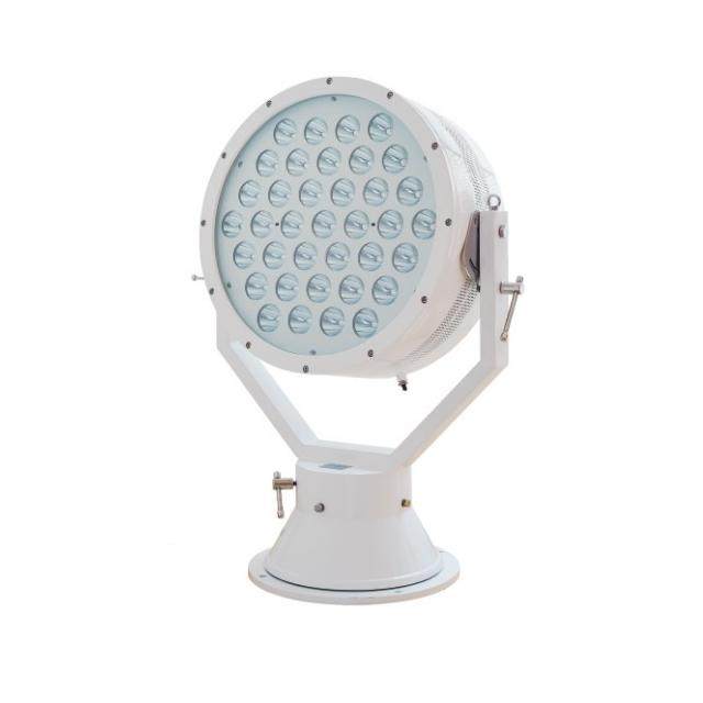
When evaluating marine searchlights, several key features should be prioritized to ensure optimal performance and longevity. Brightness, measured in lumens, is a crucial factor as it determines how well the searchlight can illuminate the surrounding area. A searchlight with a long beam distance is essential for visibility over large distances, particularly in open water. Durability and build quality are equally important; look for searchlights made from corrosion-resistant materials such as marine-grade aluminum or stainless steel. Additionally, ensure the searchlight is waterproof, with an IP67 or higher rating, to withstand the harsh marine environment.
Energy efficiency is another critical consideration. Opt for searchlights with low power consumption to avoid draining your vessel’s battery. LED technology is highly recommended due to its high brightness and energy efficiency. Adjustability and control are also important features; searchlights with 360-degree rotation and tilt functionality offer maximum coverage and flexibility. Remote control options or integration with your vessel’s navigation system can further enhance usability.
Types of Marine Searchlights
Understanding the different types of marine searchlights can help you choose the right one for your needs. Fixed searchlights, which are permanently mounted on the vessel, provide consistent illumination in a specific direction and are ideal for navigation and docking. Remote-controlled searchlights, operated via a remote control or joystick, offer flexibility and precision, making them perfect for search and rescue operations or security purposes. Handheld searchlights are portable and versatile, useful for emergencies or small vessels, but it’s essential to ensure they are waterproof and have a long battery life. Combination searchlights, which combine multiple functions such as spotlights and floodlights, offer versatile use and can be a valuable addition to any vessel.
Compliance with Maritime Standards
Ensuring that the searchlight complies with maritime safety standards and regulations is crucial. Look for searchlights that meet the standards set by organizations such as the International Maritime Organization (IMO) or the American Boat and Yacht Council (ABYC). Compliance with these standards ensures that the searchlight meets the necessary safety and performance requirements for marine use.
Budget Considerations
While it may be tempting to opt for the cheapest option, investing in a high-quality marine searchlight can save you money in the long run by reducing maintenance and replacement costs. It’s important to balance your budget with the searchlight’s features, durability, and warranty. A higher initial investment in a reliable, durable searchlight can provide greater value over time.
Brand Reputation and Reviews
Researching reputable brands known for producing reliable marine equipment is another essential step. Reading customer reviews and testimonials can provide valuable insights into the searchlight’s performance and durability in real-world conditions. Brands with a strong reputation for quality and customer support are generally a safer bet.
Warranty and After-Sales Support
Choosing a searchlight with a comprehensive warranty and reliable after-sales support is crucial. A good warranty can provide peace of mind, knowing that you can get assistance or replacements if issues arise. Reliable after-sales support ensures that you have access to technical assistance and spare parts when needed.
Where to Buy
Finally, purchasing marine searchlights from authorized dealers, marine supply stores, reputable online retailers or direct from marine lighting manufacturers on their offical websites is recommended. Avoid counterfeit or low-quality products by verifying the seller’s credibility and ensuring they offer genuine, high-quality searchlights.
Conclusion
Efficiently buying a marine searchlight requires careful consideration of your vessel’s needs, the searchlight’s features, and your budget. By focusing on durability, brightness, adjustability, and compliance with maritime standards, you can select a searchlight that enhances safety and performance on the water. Investing in a high-quality marine searchlight not only ensures visibility in challenging conditions but also provides peace of mind during your maritime adventures. Whether you’re navigating through fog, docking at night, or conducting search and rescue operations, the right marine searchlight is an indispensable tool for any vessel.
In laboratory settings, mixing and agitation of substances are fundamental tasks that can influence the outcome of experiments, analyses, and research. Among the various tools available for this purpose, orbital shakers and vortex mixers are two of the most commonly used devices. While both serve the purpose of mixing liquids or suspensions, they operate differently and are suited to specific tasks. In this article, we’ll explore the differences between an orbital shaker and a vortex mixer, their key features, and their ideal applications in laboratory environments.
What is an Orbital Shaker?
An orbital shaker is a laboratory instrument used for continuous and uniform mixing of liquids, often in flasks, tubes, or beakers. The shaker’s motion involves a circular or orbital motion, where the container moves in small, circular paths. This motion provides a gentle yet effective agitation, making it ideal for tasks that require consistent mixing over longer periods of time.
Key Features:
Orbital Motion: The platform moves in a circular motion, typically ranging from 20 to 300 rpm (revolutions per minute), although higher or lower speeds may be available depending on the model.
Adjustable Speed: Most orbital shakers allow users to adjust the speed of agitation, depending on the sensitivity of the samples and the type of mixing required.
Temperature Control (Optional): Many orbital shakers come with a built-in temperature control system, which is useful for experiments that require a specific temperature range during mixing.
Capacity: Orbital shakers can accommodate a variety of containers, from small test tubes to large flasks or multi-well plates.
Long-Run Mixing: Ideal for extended periods of agitation, orbital shakers are often used for incubations or growing cultures where constant mixing is required.
Applications of Orbital Shakers:
Cell Culture: Commonly used in microbiology and biotechnology labs for growing bacterial or mammalian cultures that require consistent aeration and mixing.
Protein Precipitation: For gently mixing samples where protein aggregates or precipitates are being formed or dissolved.
Chemical Reactions: Ideal for reactions that require sustained and gentle mixing over a long period.
Solubility Studies: Used for mixing solvents and solutes to ensure even dissolution over time.
What is a Vortex Mixer?
A vortex mixer, on the other hand, is designed for rapid and intense agitation of small sample volumes. It works by creating a rapid, circular motion that generates a “vortex” in the center of the sample. The vortex mixer typically operates by placing a test tube or flask on the device, where the mixer’s action causes the liquid in the container to spin quickly, thoroughly mixing the contents.
Key Features:
High-Speed Mixing: Vortex mixers operate at higher speeds than orbital shakers, typically ranging from 1000 to 3000 rpm.
Compact Design: Vortex mixers are typically small, handheld devices that can easily fit on a laboratory bench or workspace.
Variable Speed Control: Many vortex mixers offer adjustable speed control to fine-tune the intensity of mixing.
Touch Activation (Optional): Some vortex mixers are designed with a touch feature, where the user presses down gently on the sample container to activate the vortex, making them convenient for quick, hands-free mixing.
Applications of Vortex Mixers:
Cell Lysis: Used to rapidly break open cells to release their contents in molecular biology applications.
Sample Homogenization: Ideal for mixing small amounts of liquids or powders, especially when fast and intense agitation is required.
Reagent Mixing: Perfect for quickly mixing reagents, buffers, or blood samples in clinical and research labs.
Suspension Mixing: Commonly used to mix particles in suspension or emulsions, where a vigorous and rapid mixing action is needed.
Key Differences Between Orbital Shakers and Vortex Mixers
1. Motion Type:
Orbital Shakers: They move the sample in a circular, orbital motion. This gentle, even movement is ideal for continuous and uniform mixing.
Vortex Mixers: They create a rapid, swirling vortex in the center of the container, which is ideal for quick, intense agitation of small sample volumes.
2. Mixing Speed:
Orbital Shakers: Operate at lower to moderate speeds, typically ranging from 20 to 300 rpm, allowing for steady and gentle mixing.
Vortex Mixers: These mix at much higher speeds, usually between 1000 to 3000 rpm, producing intense, short bursts of mixing.
3. Sample Size:
Orbital Shakers: Can accommodate larger containers like flasks, beakers, or multi-well plates, and are suitable for larger sample volumes.
Vortex Mixers: Designed for small sample volumes, such as test tubes, microcentrifuge tubes, and vials, making them ideal for quick mixing of small amounts of liquid.
4. Mixing Duration:
Orbital Shakers: Typically used for long-duration mixing, sometimes over hours, making them ideal for incubations, cell cultures, or solubility studies.
Vortex Mixers: Provide short, rapid mixing durations (usually a few seconds), perfect for quickly homogenizing or mixing reagents.
5. Temperature Control:
Orbital Shakers: Many models come with built-in heating systems, which is useful for experiments that require temperature control while mixing.
Vortex Mixers: Do not typically offer temperature control, as they are meant for quick mixing of small samples.
6. Device Size and Versatility:
Orbital Shakers: Larger in size, with a flat platform that can hold various containers, such as flasks, tubes, and plates, making them versatile for different experiments.
Vortex Mixers: More compact and typically designed for specific containers like test tubes, offering a more focused and intense mixing action.
Choosing the Right Mixer for Your Lab
The choice between an orbital shaker and a vortex mixer depends on the specific needs of the experiment, the sample type, and the desired results. Here’s a guide to help you decide:
Use an Orbital Shaker If:
You need to mix larger volumes of liquid.
The experiment requires continuous and gentle mixing over a long period.
You are working with cell cultures, enzyme reactions, or protein dissolution.
Temperature control is essential for your experiment (e.g., incubating cells or reactions).
The task involves shaking a variety of containers or multi-well plates.
Use a Vortex Mixer If:
You need rapid mixing of small samples or reagents.
You’re working with test tubes or microcentrifuge tubes and need quick agitation.
Your samples require intense mixing, such as breaking down cellular structures or suspending solids.
You need a compact, easy-to-use device that doesn’t require long-duration agitation.
Speed and intensity are more important than gentle mixing.
Conclusion
Both orbital shakers and vortex mixers play pivotal roles in laboratory mixing and agitation, each suited to different tasks and sample types. The orbital shaker excels in continuous, gentle mixing of larger volumes, ideal for tasks that require sustained agitation over a long period. In contrast, the vortex mixer is perfect for rapid, intense mixing of small sample volumes, offering quick results when high-speed agitation is needed. Understanding the differences between these two devices allows lab professionals to select the right equipment for their specific needs, ensuring both efficiency and the quality of experimental outcomes.
Inflatable life rafts are critical safety equipment designed to provide buoyancy and shelter in emergency situations at sea. They offer a quick and reliable means of survival during maritime accidents, and their lightweight and compact nature make them indispensable on commercial vessels, yachts, and other marine craft. One of the key concerns with inflatable life rafts, however, is their vulnerability to damage. From punctures to tears, the integrity of the raft can be compromised in harsh conditions.
To address this issue, manufacturers have begun integrating self-repair features into inflatable life rafts, improving their durability and enhancing their life-saving capabilities. These innovations help ensure that even if the raft is damaged, it remains operational and effective in an emergency.
What Are Self-Repair Features in Inflatable Life Rafts?
Self-repair features refer to the raft’s ability to fix or seal small holes and punctures without requiring immediate human intervention. These features can be built into the design of the life raft itself and generally involve the use of specialized materials and technologies that activate when damage occurs. The aim is to keep the life raft inflated and functional, providing an additional layer of safety for those relying on it.
Key Self-repair Features Integrated into Inflatable Life Rafts
1. Self-Sealing Fabric Technology
Self-sealing fabrics are one of the most effective innovations in inflatable life rafts. These fabrics are coated with specialized materials that can automatically close up when punctured. When the fabric is damaged, the sealant material inside the fabric’s layers reacts with the surrounding air or moisture, forming a temporary bond that prevents the loss of air. While not always a permanent solution, this self-healing action can allow the raft to remain functional long enough to reach safety.
How it works:
Puncture Occurrence: When the raft’s fabric is punctured or torn, the exposed edges of the material begin to react with air, triggering a sealing mechanism.
Seal Formation: The sealant within the fabric works to close the puncture, reducing the rate of deflation.
Temporary Inflation Maintenance: This process helps to maintain the raft’s buoyancy, even in the event of minor damage.
This self-sealing feature significantly reduces the risk of complete deflation, offering peace of mind to those relying on the raft.
2. Integrated Patch Kits with Automatic Inflation
Some advanced inflatable life rafts are designed with integrated repair kits that can be used automatically or manually to seal leaks. These kits typically contain patches, adhesives, and instructions for repairing the raft in the event of damage. However, the next generation of self-repair systems can apply these patches automatically.
How it works:
Puncture Detection: The life raft may have built-in sensors or an automatic system that detects when a puncture occurs.
Patch Deployment: Upon detection of a leak, a small patch or adhesive layer is released from a compartment and applied directly over the damaged area.
Re-Inflation: Once the patch is in place, the raft’s internal inflation system can be activated to restore air pressure, ensuring that the raft remains fully functional.
These systems not only make repairs quick and efficient but also remove the need for immediate action from the raft’s occupants, allowing them to focus on survival instead of dealing with the raft’s integrity.
3. Reinforced Seams and Double-Layered Construction
Many inflatable life rafts feature reinforced seams and double-layered construction to improve overall strength and resilience. These additional layers of material act as a safeguard in the event of punctures, ensuring that any damage is contained within the outer layer, leaving the inner layers intact.
How it works:
Dual Layers: The raft consists of two layers of fabric, with the inner layer often serving as a backup in case the outer layer is damaged.
Reinforced Seams: High-stress areas, such as seams, valves, and corners, are reinforced to prevent tearing and separation.
Minimal Air Loss: Even if the outer layer is compromised, the inner layer continues to hold air, preventing rapid deflation.
This feature improves the raft’s durability and makes it much less susceptible to damage from rough sea conditions or sharp objects.
4. Sealed Air Chambers with Independent Inflation Systems
Many advanced inflatable life rafts come equipped with multiple air chambers that are independently inflated. These chambers can be repaired or inflated separately, which allows the raft to remain operational even if one or more chambers suffer damage.
How it works:
Independent Inflation: The raft has multiple, isolated air chambers, each of which can be inflated and deflated independently of the others.
Damage Containment: If one chamber is damaged, the others will continue to provide buoyancy, reducing the risk of total deflation.
Ease of Repair: Even if a chamber is punctured, it can be manually inflated or repaired without affecting the rest of the raft.
This system ensures that damage to one part of the raft does not compromise its overall functionality, thus enhancing safety and stability in emergency situations.
5. Automatic Re-inflation Mechanisms
There are automatic re-inflation mechanisms in some life rafts designed to activate when a drop in air pressure is detected. These mechanisms can be triggered by sensors that monitor the raft’s buoyancy and air volume. Once a leak is identified, the system will release additional air or activate the raft’s internal inflation system to restore the necessary air pressure.
How it works:
Pressure Monitoring: The life raft continuously monitors the internal air pressure.
Leak Detection: If a pressure drop is detected, the system automatically activates the inflation mechanism to compensate for the loss.
Constant Buoyancy: This ensures that the life raft remains adequately inflated, even after a puncture, and can continue to support the occupants.
This feature is particularly useful in life rafts that are exposed to harsh sea conditions where punctures and air loss are more likely to occur.
6. Durable Materials and Coatings
The durability of the materials used in inflatable life rafts plays a crucial role in preventing punctures and enhancing the raft’s ability to self-repair. Many rafts are made from high-quality, abrasion-resistant fabrics such as Hypalon or PVC, which are resistant to UV degradation, tearing, and puncturing. Some rafts also have special coatings that further enhance their self-repair capabilities.
How it works:
Abrasion Resistance: The materials used in the raft’s construction are resistant to wear and tear, reducing the chances of damage in the first place.
Chemical Resistance: Some coatings are designed to resist oil, fuel, and other chemicals, which could otherwise damage the material and compromise its buoyancy.
Extended Lifespan: These durable materials increase the lifespan of the raft, meaning it can endure more extreme conditions before repairs are needed.
Summary
Self-repair features in inflatable life rafts represent a significant step forward in maritime safety. By integrating innovative technologies like self-sealing fabrics, automatic re-inflation, and reinforced materials, modern inflatable life rafts offer an enhanced level of reliability that ensures they will remain functional even in challenging emergency situations. These advancements not only make life rafts more resilient but also provide peace of mind for those who depend on them for survival at sea. As maritime safety continues to evolve, self-repair technologies will undoubtedly play a pivotal role in ensuring that inflatable life rafts remain a vital and effective tool in life-saving scenarios.
Web guiding systems play a crucial role in industries such as printing, packaging, textiles, and battery manufacturing, where precise alignment of flexible materials is essential. However, handling flexible materials—such as thin films, foils, and nonwovens—introduces challenges due to their low stiffness, sensitivity to tension variations, and environmental influences. Addressing these challenges in web guiding for handling flexible materials requires advanced control systems, high-precision sensors, and adaptive automation.
Challenges in Web Guiding for Flexible Materials
1. Material Deformation and Wrinkling
Flexible materials are prone to wrinkling due to uneven tension distribution, variations in material thickness, and surface inconsistencies. Wrinkling can lead to quality defects and production inefficiencies.
2. Tension Instability and Edge Curling
Maintaining uniform tension is difficult with low-stiffness materials, which can stretch, sag, or curl at the edges. Tension fluctuations can cause misalignment, affecting downstream processes such as coating and printing.
3. Sensor Limitations for Material Detection
Detecting the edges or center of flexible materials can be challenging, especially for transparent, reflective, or perforated surfaces. Conventional sensors may struggle to provide accurate readings, leading to guiding errors.
4. High-Speed Processing Issues
At high production speeds, minor misalignments can escalate into significant defects, increasing material waste and requiring frequent machine stoppages for corrections.
5. Environmental Influences on Web Stability
Temperature fluctuations, humidity changes, and static electricity can affect material behavior. High humidity can cause materials to expand or stick together, while static buildup can lead to erratic movement.
6. Multi-Material Handling Challenges
Production lines often process multiple types of flexible materials with different mechanical properties. A one-size-fits-all guiding system may not provide optimal alignment for all materials, requiring frequent manual adjustments.
Solutions for Effective Web Guiding
1. Adaptive Tension Control Systems
Maintaining uniform tension across the web is critical for preventing deformation and misalignment. Advanced tension control solutions include:
Closed-Loop Tension Control – Sensors continuously monitor tension levels, and automated feedback systems adjust rollers or brakes to maintain stability.
Load Cells and Dancer Rolls – These components help regulate tension by compensating for variations in material elasticity and speed.
Zonal Tension Adjustments – Multi-zone tension control ensures that different sections of the material maintain optimal tension, reducing edge curl and web distortion.
2. High-Precision Sensor Technologies
Accurate material detection is essential for effective web guiding, especially for transparent, reflective, or porous materials. Advanced web guide sensors include:
Infrared Sensors – Ideal for detecting materials with varying opacity, improving alignment accuracy.
Ultrasonic Sensors – Effective for guiding nonwoven and perforated materials where optical sensors may struggle.
Vision-Based Sensors – High-resolution cameras with AI-driven edge detection enhance accuracy, even in high-speed operations.
3. Advanced Edge and Center Guiding Systems
Web edge guiding systems adjust material alignment based on real-time edge or center position detection. Effective solutions include:
Edge Guiding Systems – Utilize sensors to track the material’s edge and automatically correct its position through actuator-controlled rollers.
Center Guiding Systems – Maintain the web’s center alignment, ideal for applications requiring precise symmetrical positioning.
Hybrid Guiding Systems – Combine edge and center guiding to handle materials with irregular edges or varying widths.
4. Real-Time Feedback and Closed-Loop Control
Modern web guiding systems integrate closed-loop control mechanisms, which continuously adjust guide rollers based on sensor feedback. These systems:
Reduce Response Time – Minimize deviations by making real-time corrections.
Enhance Process Stability – Maintain alignment even at high production speeds.
Integrate with Automation – Connect with PLCs and Industry 4.0 platforms for predictive adjustments and process optimization.
5. Smart Guide Actuators for High-Speed Operations
Flexible materials require responsive actuators to prevent misalignment, especially at high speeds. Smart actuators offer:
Fast-Response Correction – Adjust web position within milliseconds.
Low-Friction, High-Precision Movement – Ensures smooth operation without damaging delicate materials.
6. Static Elimination and Environmental Compensation
Environmental factors like static electricity, temperature, and humidity can affect web stability. Effective countermeasures include:
Anti-Static Devices – Ionizers and grounding bars neutralize electrostatic charges to prevent web sticking or misalignment.
Climate Control Systems – Maintain consistent temperature and humidity levels to reduce material expansion or contraction.
Material-Specific Compensation – Adaptive control systems adjust guiding parameters based on environmental conditions.
7. AI-Driven Automation and Predictive Maintenance
Industry 4.0 advancements have enabled AI-powered web guiding solutions that enhance efficiency and minimize downtime. Key features include:
Machine Learning Algorithms – Automatically adjust guiding parameters based on historical data and real-time conditions.
Predictive Maintenance Alerts – Identify potential wear or system failures before they cause disruptions.
Remote Monitoring and Control – Cloud-based systems allow operators to monitor and adjust web guiding settings remotely.
Conclusion
Handling flexible materials in web guiding systems presents challenges such as tension instability, wrinkling, and sensor detection limitations. Implementing advanced solutions—such as real-time feedback control, AI-driven automation, precision sensors, and adaptive tension management—can significantly improve guiding accuracy, reduce waste, and enhance production efficiency.