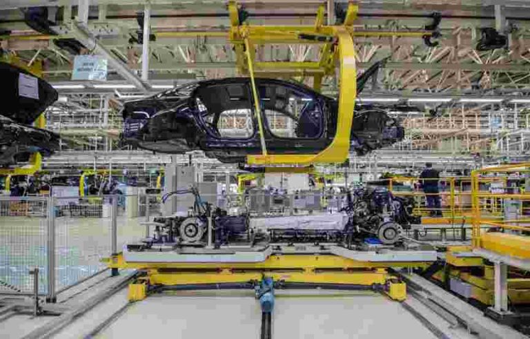
In industries characterized by continuous material processing—such as printing, converting, packaging, and textiles—meticulous control of web tension and web alignment is paramount. These controls are essential to ensure product quality and optimize production efficiency. This article delves into the integration of web tension controllers with automated web guiding systems, shedding light on the advantages and diverse applications of this innovative combination.

Understanding Web Tension Controllers
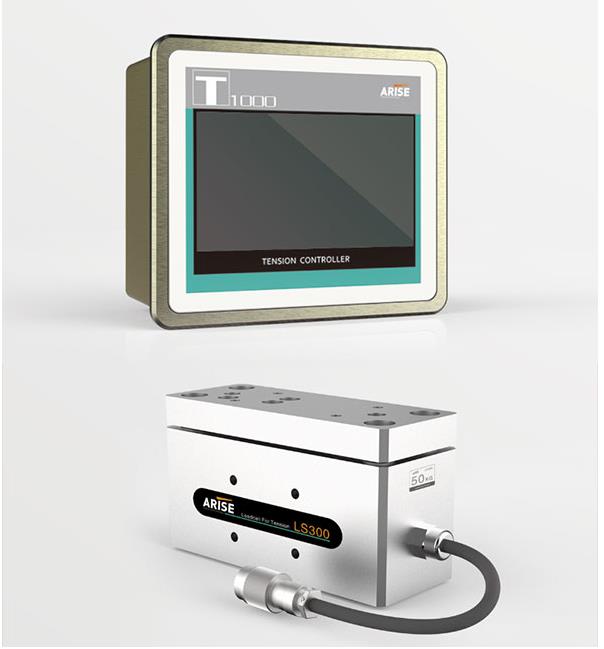
Web tension, often associated with materials in roll form or web format, pertains to the uniformity and consistency of material as it traverses the manufacturing process. Maintaining precise web tension is critical to prevent defects, control printed materials accurately, and avert web breakages. Web tension controllers are instrumental in achieving and sustaining the desired level of tension. These controllers operate by modulating the speed or torque of components like motors, brakes, or clutches to maintain the material’s tension within the specified range.
The Role of Web Guiding Systems
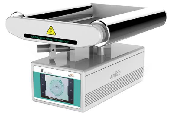
Web guiding systems are specialized machines dedicated to ensuring the alignment and positioning of continuous webs of materials as they progress through various industrial machines and processes. These materials can encompass paper, film, fabric, metal, and more. Web guiding systems are pivotal in keeping web materials centered, aligned, and free from defects as they traverse the production line.
Web guide control systems find application in numerous industrial processes where precise alignment and management of continuous materials or webs are indispensable for maintaining product quality and process efficiency. These systems play a critical role across a wide spectrum of industries, including printing, converting, packaging, textiles, and paper manufacturing.
Key Components of Web Guiding Systems
Web Sensors: These sensors detect the position or alignment of the web material. Common web guide sensors include edge sensors, line sensors, or contrast sensors, selected based on the material type and process.
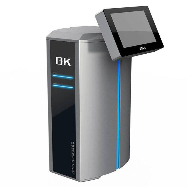
Controller: The web guiding controller processes sensor inputs and determines the necessary adjustments to maintain proper web alignment. It then transmits control signals to actuators.
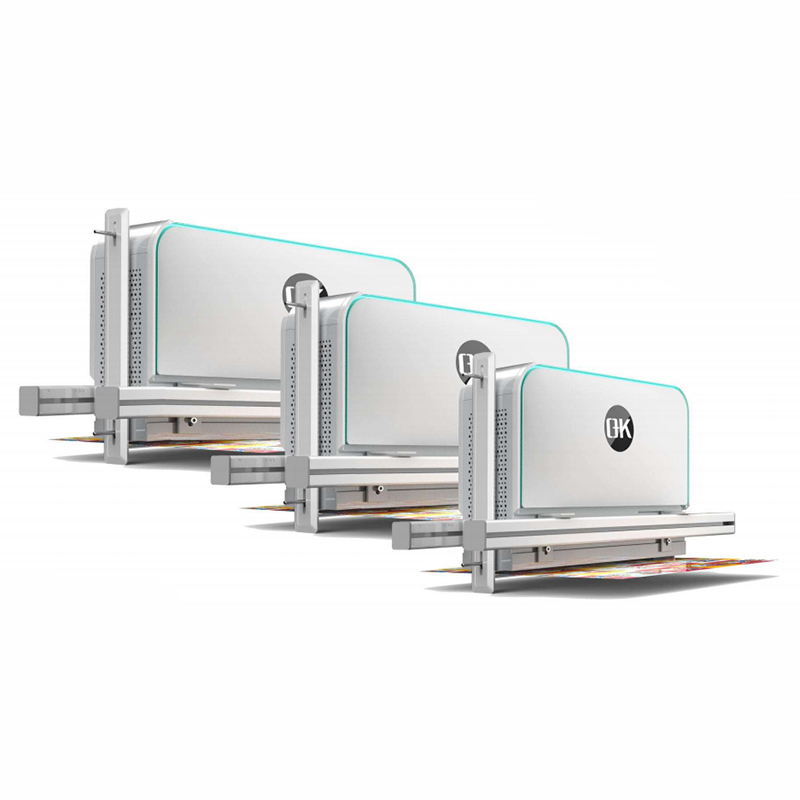
Actuating Devices: Actuators, such as steering guides, rollers, or moving frames, physically alter the position of the web material in response to the controller’s directives.
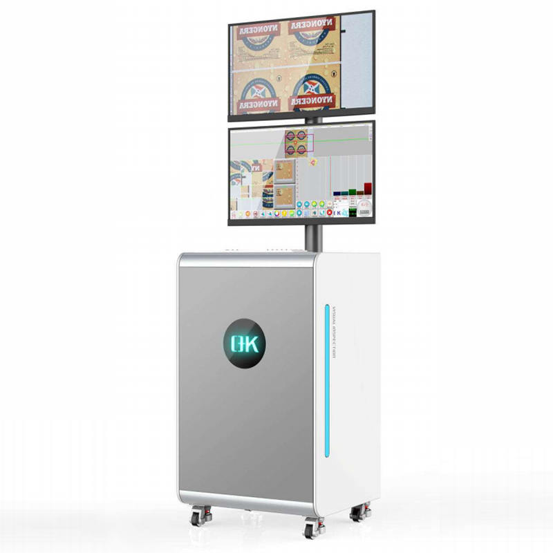
User Interface: Some web guiding machines provide user interfaces, enabling operators to configure parameters, monitor system performance, and make manual adjustments as needed.
Advantages of Integrated Web Tension Controllers with Web Guiding Systems
The integration of web tension controllers with automated web guiding systems offers several notable advantages:
Precise Control: The combination delivers real-time tension control and ensures precise alignment and tracking of materials, resulting in high-quality finished products.
Reduced Waste: By preventing misalignment and over-tensioning, these integrated systems minimize material waste, reducing defects and web breakages.
Enhanced Efficiency: Automation reduces the need for manual interventions, enhancing overall productivity as operators can focus on other critical aspects of the manufacturing process.
Improved Product Quality: Consistent tension and alignment throughout the process significantly enhance the quality of finished products, whether it involves printing, laminating, coating, or slitting.
Versatility: These systems are adaptable and can integrate seamlessly into various machines and processes, making them suitable for a wide range of industries and applications.
Common Applications of Integrated Web Tension Controllers with Web Guiding Systems
Printing: Precise tension and alignment control are pivotal in the printing industry to produce accurately printed materials with high quality.
Packaging: Integrated systems ensure proper cutting, folding, and sealing of package materials, reducing waste and optimizing packaging quality.
Textiles: Textile manufacturers rely on these integrated systems to maintain consistent tension and alignment of fabrics, preventing defects and improving the quality of end products.
Converting: In the converting industry, where materials undergo transformation into various products, integrated systems ensure accurate and efficient processing at each stage.
Labeling: Precision web tension and web guiding are critical in label printing and application to achieve correctly positioned and securely attached labels on items.
Conclusion
The integration of web tension controllers with web guiding systems marks a significant technological advancement in manufacturing. In diverse industries, these integrated systems play a pivotal role in enhancing efficiency, reducing waste, and elevating product quality. As technology continues to advance, we can anticipate further innovations in web tension and web guiding control, driving the manufacturing industry toward increased automation and precision.