Aerospace bolts play a vital role in transferring shear and tensile loads, finding extensive application in areas that bear heavy concentrated loads or require disassembly within the realm of aviation. In this article, we explore the standards governing bolt threads in the aerospace industry, offering insights into the various specifications, fit quality, and identification symbols. These standards provide essential guidelines for selecting the right bolts for aviation applications.
1. Standards for Bolt Threads
In the aerospace industry, the standards for bolt threads are critical for ensuring the safety and integrity of aircraft structures. There are several key standards to consider:
a. American National Coarse Threads
b. American National Fine Threads
c. American Standard United Coarse Threads
d. American Standard United Fine Threads
These standards differentiate primarily based on two key factors:
1. Thread Pitch: Coarse and fine series threads of the same size share the same nominal thread diameter but differ in the number of threads per inch.
2. Tolerance Distribution: Each standard has distinct tolerance specifications for threads with a one-inch diameter. For instance, NF regulation utilizes 14 teeth per inch, represented as 1-14NF, while UNF regulation employs 12 teeth per inch, represented as 1-12UNF.
2. Fit Quality
The grade of a thread indicates the tightness of the fit between threaded parts, and it ranges from Grade 1 to Grade 5:
a. Grade 1 (Loose Fit): This level of fit allows for easy manual turning of the nut.
b. Grade 2 (Free Fit): Typically used for aerospace screws due to its specific requirements.
c. Grade 3 (Medium Fit): Commonly used for aerospace bolts where a secure yet manageable fit is essential.
d. Grade 4 and 5 (Tight Fit): These grades require a wrench for nut tightening. A higher grade corresponds to a tighter fit.
3. Identification Symbols
Bolt identification includes details such as diameter, length, and material. The unit of measurement for diameter is 1/16 inch, while the unit for bolt rod length is 1/8 inch. Material specifications are conveyed using English letters or symbols:
“C” denotes stainless steel.
“DD” signifies 2024 aluminum alloy.
“-” is used for nickel alloy steel.
General Standard Bolts in the Aerospace Industry
Hexagonal Head Bolt
The hexagonal head bolt is a widely used standard aviation bolt suitable for aircraft structure assembly, capable of withstanding tensile and shear loads. It adheres to the AN model specification standard and employs fine threads. Materials include chrome-plated nickel steel, stainless steel, and 2024 aluminum alloy.

Model Specification Code:
Example: AN 3 DD 14A
“AN” represents the standard bolt of USAF Navy specification.
“3” denotes a bolt diameter of 3/16 inch.
“DD” indicates the use of 2024 aluminum alloy.
“14” signifies a rod length of 1.5 inches.
“A” indicates the absence of a safety hole at the screw tail.
Engine Bolts Drilled in the Head
These bolts, identified by model specification codes ranging from AN73 to AN81 and MS20073 to MS20074, have slightly thicker heads with a through hole for a fuse. They possess the same tensile and shear strength as ordinary bolts.
Hexagon Socket Head Bolt
These bolts, bearing model specification codes MS20004 to MS20024, come in various diameters from 4/16 inch to 24/16 inch. They are made of high-strength steel and are not interchangeable with AN series hexagon bolts. These bolts are primarily used for connecting parts that bear both tensile and shear combined stresses.
For steel parts, the installation hole should be chamfered to allow the fillet to sink into the hole.
When installing on aluminum alloy parts, an MS20002C washer should be used beneath the bolt head.
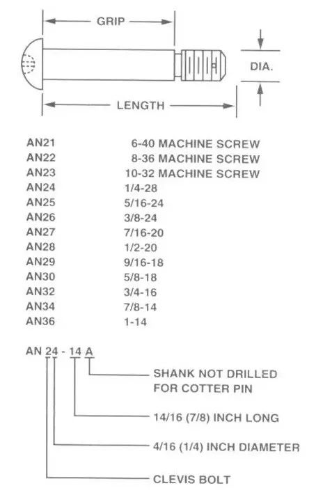
Slotted Cheese Head Bolt
Slotted cheese head bolts are identified by model specification codes like AN21, AN22, and AN23, where the digits represent thread sizes (e.g., “6-40,” “8-36,” “10-32”). These bolts have fine threads (NF) and are ideal for bearing shear loads, often used as hinge pivot pins in rotating parts.
In Conclusion
Understanding the standards for bolt threads in the aerospace industry is crucial for selecting the right fasteners for aviation applications. The specifications, fit quality, and identification symbols of these bolts ensure the safety and reliability of aerospace structures. Proper bolt selection is an essential aspect of aviation engineering, contributing to the overall safety and performance of aircraft.