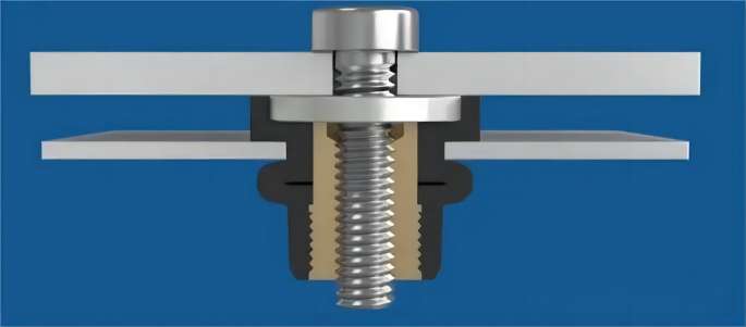
In recent years, rivet nuts have emerged as revolutionary fasteners, designed to address the challenges associated with welding nuts for thin metal sheets and pipes. Developed to combat issues such as melting during welding and slipping internal threads, rivet nuts offer a practical and efficient solution. This article provides an in-depth exploration of rivet nuts, covering types, advantages, and essential precautions for their effective use.
Types of Rivet Nuts:
Rivet nuts are diverse, classified based on material, head type, column, and hole type:
Material:
316 Stainless Steel
316L Stainless Steel
v304 Stainless Steel
Carbon Steel (08A)
Aluminum
Copper
Head Types:
Flat Head
Countersunk Head
Small Countersunk Head
Flat Head Hexagon
Countersunk Hexagon
Column Types:
Common Round Type
Knurled Round Type
Full Hexagon Type
Semi-Hexagon Type
Hole Types:
Open Type
Closed Type
Advantages of Using Rivet Nuts:
Rivet nuts offer numerous advantages, making them indispensable in various industries:
Versatile Connection:
Ideal for connecting non-structural load-bearing bolts, especially in applications like interior trim parts in railway passenger cars and highway passenger cars.
Surface Coating Compatibility:
Rivet nuts and studs can be installed at any production stage, even on coated or painted surfaces, without the need for additional surface treatment.
Temperature Resistance:
Rivet nuts and studs are not affected by high temperatures during installation, ensuring no damage to components.
Safety and Environmental Benefits:
No harmful gas emission or fire hazard, ensuring a safe working environment and guaranteeing the safety of manufacturers.
Economic Advantages:
Rivet nuts boast economic advantages, requiring less time for production, low costs, and offering overall cost-effectiveness.
Precautions for Using Rivet Nuts:
While rivet nuts offer a seamless solution, attention to certain precautions is crucial during their use:
Equipment Assembly:
Ensure correct assembly of the equipment’s mouth screw. Select the appropriate equipment head and rivet bolt based on the dimensions of the rivet nut, verifying the firm connection of connecting parts.
Deformation and Adjustment:
Pay attention to the deformation length or displacement of the riveted nut and adjust the operating lever angle accordingly.
Scale Ring Adjustment:
Use the scale ring to adjust the rivet stroke during operation. When adjusting the length of the rivet bolt, open two handles and adjust the equipment head sleeve for optimal length.
Proper Assembly Sequence:
Follow a specific sequence during assembly, ensuring the nut is squeezed firmly onto the rivet bolt and properly inserted into the pre-drilled hole.
Equipment Maintenance:
Regularly check for loose caps during the operation of manual rivet nut equipment. Tighten them promptly and protect equipment head bolts from damage after use.
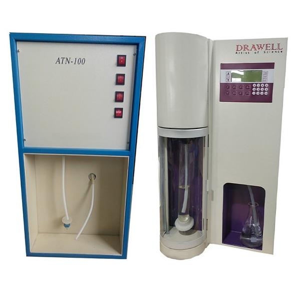
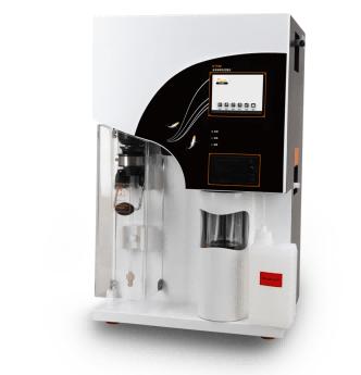
Kjeldahl nitrogen analyzers play a crucial role in laboratories, facilitating the accurate determination of nitrogen content in various substances. However, like any complex instrument, these analyzers can encounter issues during operation. This article aims to provide a comprehensive guide to common problems associated with Kjeldahl nitrogen analyzers and practical solutions to address them.
Violent Rolling During Distillation:
Issue: The Kjeldahl nitrogen analyzer rolls violently during distillation.
Solution: This is typically caused by a large amount of water vapor entering the digestive tube. While it may appear concerning, the Kjeldahl nitrogen analyzer is equipped with an overpressure protection device to maintain safe internal pressure.
Water Quality Requirements:
Issue: What are the water quality requirements for the Kjeldahl nitrogen analyzer?
Solution: Use distilled water or pure water in the distilled water barrel. If the analyzer is unused for an extended period, release the water in the distiller.
No Sound When Turned On:
Issue: The Kjeldahl nitrogen analyzer produces no sound when turned on.
Solution: Check if the red light on the power switch is on. If the fuse is blown, locate it in the black case 5 cm away from the power switch interface inside the machine.
Failure to Add Water to the Distiller:
Issue: The Kjeldahl nitrogen analyzer does not add water to the distiller after being turned on.
Solution: Check for leaks in the distilled water bucket, ensure the water level is sufficient, and verify correct connections. Confirm that the drain valve is closed.
Steamer Not Heating:
Issue: The steamer of the Kjeldahl nitrogen analyzer does not heat and cannot produce steam.
Solution: If alkali can be added but no steam is produced, the heating wire may be burnt out. Use a multimeter to check the positive and negative electrodes.
Loud Working Sound:
Issue: The Kjeldahl nitrogen analyzer produces a loud working sound.
Solution: This is a normal sound resulting from the air pump inside the analyzer.
Failure to Add Alkali:
Issue: The Kjeldahl nitrogen analyzer cannot add alkali, and there is no sound during the process.
Solution: Check for alkali barrel leaks and ensure the machine operates normally when inflated with air. If the analyzer has been in use for a long time, crystallization inside the alkali pipe may impede flow.
Smoke-Like Gas Emission:
Issue: Smoke-like gas comes out from the top during operation.
Solution: Ensure the cooling water inlet faucet is open. Closed or low water volume can result in uncondensed steam, creating the appearance of smoke.
Sucking Back of White Tube:
Issue: The white tube in the digestive tube sucks back during operation.
Solution: Check if the gas valve closes promptly when the Kjeldahl nitrogen analyzer stops working. If not, pierce small holes in the white tube or replace the faulty air valve.
Regular Sound Every 3-5 Seconds:
Issue: The Kjeldahl nitrogen analyzer makes a sound every 3-5 seconds during operation.
Solution: This periodic sound is normal. It occurs as the distiller continues to heat, generating water vapor, and the machine automatically opens the water valve to replenish water.
Conclusion
Troubleshooting common problems in Kjeldahl nitrogen analyzers involves a systematic approach to identify and address issues promptly. By understanding the potential challenges and implementing the provided solutions, operators can ensure the reliable and efficient performance of these essential laboratory instruments. Regular maintenance and adherence to operational guidelines contribute to the longevity and accuracy of Kjeldahl nitrogen analyzers in analytical processes.
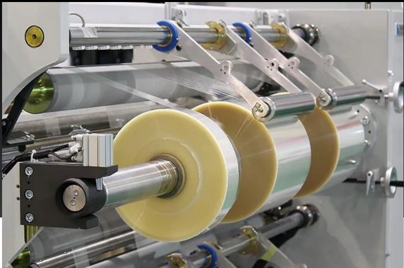
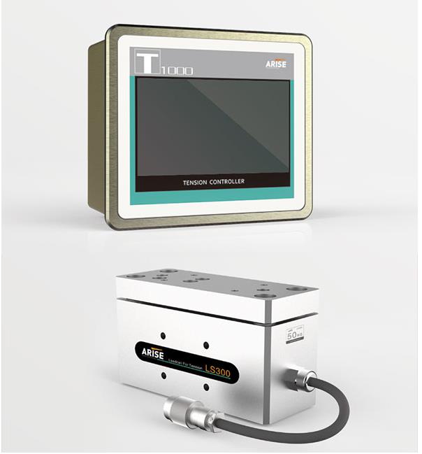
In today’s rapidly evolving industrial landscape, where efficiency and cost-effectiveness are paramount, the need to meet production demands often requires the utilization of older machinery in sectors like printing, packaging, and textiles. However, while these machines may still be operational, their outdated features and lack of modern technology can hinder productivity and compromise product quality. The solution? Retrofitting older machines with web tension control systems, a pragmatic alternative that brings outdated equipment up to modern standards.
The Significance of Retrofitting with Web Tension Control Systems:
Web tension control is a critical element in manufacturing processes involving continuous materials such as paper, film, fabric, or metal. Ensuring the precise movement of materials through a machine is essential for maintaining product quality, minimizing waste, and reducing downtime.
Benefits of Retrofitting with Web Tension Control Systems:
1. Improved Product Quality:
Consistent web tension leads to fewer faults, translating to higher-quality goods that enhance a company’s reputation and client satisfaction.
2. Enhanced Efficiency:
Reduced downtime and increased production rates contribute to overall efficiency, directly impacting the bottom line of manufacturing operations.
3. Cost Savings:
Less waste, lower maintenance costs, and improved energy efficiency collectively contribute to substantial cost savings and increased profitability.
4. Sustainability:
Reduced waste and energy consumption not only save money but also align manufacturing operations with environmental sustainability goals.
5. Prolonged Machine Life:
Retrofitting can extend the life of aging machinery, postponing the need for expensive replacements and providing a sustainable approach to equipment management.
6. Data-Driven Decision Making:
Modern tension control systems offer valuable data and analytics, enabling informed decision-making and process optimization.
The Retrofitting Process with Web Tension Control Systems:
Assessment:
Conduct a thorough evaluation of current equipment to identify areas where web tension control is critical to the production process.
System Selection:
Choose a web tension controller based on specific needs, considering factors such as web material, machine specifications, and production speed.
Installation:
Professional installation by experts familiar with the intricacies of integrating modern control systems with older equipment. Mechanical and electrical adjustments may be necessary for compatibility.
Calibration:
Calibrate the system to provide precise tension control, including setting up sensors, establishing tension zones, and adjusting control settings.
Training:
Train operators and maintenance personnel to efficiently operate and manage the tension control system.
Integration:
Seamlessly integrate the new web tension control system into the existing control infrastructure, such as PLCs (Programmable Logic Controllers) or SCADA (Supervisory Control and Data Acquisition) systems, for streamlined communication and data exchange.
Case Studies of Retrofitting Older Machines with Web Tension Control Systems:
Case Study 1: Printing Industry – ABC Printing Company
Challenge:
Aging web offset printing press lacking precise web tension control, resulting in inconsistent print quality and frequent paper jams.
Solution:
Replacement of the antiquated press with a modern web tension control system.
Results:
Significant improvements in product quality, increased productivity, waste reduction, and simplified maintenance.
Case Study 2: Textile Industry – XYZ Textile Mills
Challenge:
Weaving looms experiencing yarn breakage, misalignment, and variable fabric quality due to the lack of precise web tension control.
Solution:
Retrofitting of weaving looms with a modern web tension control system.
Results:
Enhanced fabric quality, increased productivity, and cost savings through reduced material waste.
These case studies underscore how retrofitting older machines with modern web tension control systems can positively impact product quality, productivity, cost savings, and sustainability, making it a prudent investment for manufacturing businesses.
Conclusion:
For companies seeking to enhance the efficiency and productivity of existing production processes, retrofitting older machines with web tension control systems proves to be a strategic and cost-effective solution. This method ensures that aging machinery can compete with modern counterparts, resulting in improved product quality, waste reduction, and overall cost savings. By carefully assessing machinery, selecting the appropriate control system, and investing in professional installation and training, manufacturing operations can remain competitive and forward-looking in an ever-evolving industrial landscape.
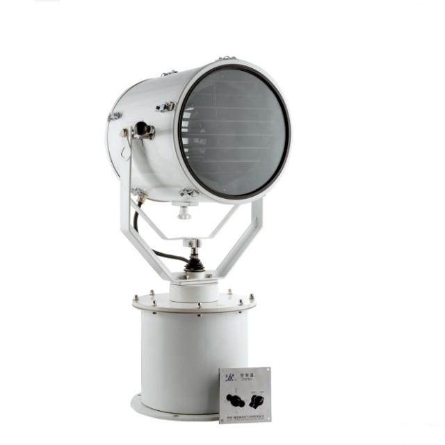
Marine lighting is far more than just a means to see in the dark waters. It is a pivotal component in the enigmatic realm beneath the ocean’s surface. Its importance spans a wide spectrum, encompassing navigational safety, scientific exploration, environmental protection, artistic expression, and the adoption of cutting-edge technologies. In this article, we delve into the captivating world of marine lighting, shedding light on its various roles, the common types it encompasses, the technological breakthroughs that are shaping its future, and its profound impact on our understanding and preservation of the world’s aquatic ecosystems.
The Crucial Role of Marine Lighting
Marine lighting plays a pivotal role in our interactions with the underwater world, serving as a guiding light for vessels and unlocking the mysteries of the deep.
Navigational Safety and Guidance
Safety on the high seas is heavily reliant on marine lighting. Lighthouses stand as iconic symbols of maritime safety, guiding ships away from treacherous shores and perilous rocks. Navigation lights on vessels, as well as strategically placed buoy lights, provide essential guidance, helping seafarers navigate safely through challenging waters.
Scientific Exploration and Discovery
Beneath the waves, marine lighting reveals a world teeming with uncharted beauty and mystery. Advanced lighting systems on submersibles, remotely operated vehicles (ROVs), and autonomous underwater vehicles (AUVs) illuminate the hidden depths, enabling researchers to capture stunning images and films of marine life, geological formations, and underwater ecosystems. These lights transform these vessels into windows into the unknown, allowing us to gain insight into a realm that has long eluded us.
Environmental Conservation and Study
Marine lighting is a crucial tool for studying and preserving intricate marine ecosystems threatened by human activities. Bioluminescent organisms, unique to the depths, emit their own light, and adequate illumination is necessary to observe and document their behavior. Controlled lighting is used by marine researchers to monitor and study marine life, deepening our understanding of biodiversity, migration patterns, and the interactions that sustain delicate ecosystems. Additionally, responsible marine lighting practices mitigate light pollution, preserving the natural behaviors of marine species and supporting conservation efforts.
Artistic Exploration and Communication
Marine lighting is not only a utilitarian tool but also a conduit for artistic expression. Underwater photographers and filmmakers employ specialized lighting equipment to capture the ethereal beauty of marine landscapes, creating visually captivating narratives that bridge the gap between the aquatic world and land-bound audiences. These artistic initiatives not only inspire awe but also foster a deeper connection between humans and the aquatic realm.
Technological Advancements and Future Prospects
The advent of LED technology, energy efficiency, and remote sensing innovations is ushering in a new era for marine lighting. These technological advancements are revolutionizing how we interact with marine environments, from reducing light pollution to harnessing renewable energy sources for illumination. As technology continues to evolve, the future of marine lighting holds the promise of more sustainable, adaptable, and environmentally friendly solutions.
The Diverse Types of Marine Lighting
Marine lighting encompasses a wide array of categories, each tailored to specific marine functions and applications.
Lighthouses have long served as beacons of safety, guiding mariners away from dangerous waters. Equipped with powerful lighting systems and distinctive patterns, they are recognizable from a distance and have become symbols of maritime history.
Buoy Lights
Buoy lights play a vital role in indicating safe navigation through waterways and channels. Their color and design convey navigational messages, directing mariners safely through treacherous waters.
Underwater Lights
Underwater lights serve multiple purposes, including illuminating underwater structures and enhancing visibility in marine environments. They are essential for observing marine life and studying delicate ecosystems while minimizing disturbances.
Research Lighting Systems
Specialized illumination systems on marine research vessels, such as ROVs and AUVs, enable scientists to capture high-definition visuals for scientific study and documentation, shedding light on the ocean’s mysteries.
Fishing and Commercial Lighting
Marine lighting is essential for the fishing and commercial industries. It helps fishing boats attract fish and ensures efficient nighttime operations for commercial vessels.
Deck and Interior Lighting
Deck and interior lighting, often underestimated, are critical for safety and functionality on vessels, making nighttime operations safer and providing a comfortable living and working environment for crew members.
Environmental and Wildlife Preservation Lighting
Emerging technologies are reducing the impact of light pollution on marine life while maintaining navigational and safety requirements.
Innovative Technological Advances in Marine Lighting
Marine lighting technology is evolving, transforming the way we illuminate the oceans and advancing navigational safety, scientific exploration, and environmental protection.
Energy-Efficient LED Lighting
The adoption of light-emitting diodes (LEDs) is a major breakthrough in marine lighting technology. LEDs offer exceptional energy efficiency, consuming significantly less electricity while providing intense and focused illumination. They contribute to sustainable maritime practices by reducing energy consumption and operational costs.
Adaptive Lighting Controls
Adaptive lighting systems adjust their intensity and color based on environmental conditions and user needs, reducing light pollution and preserving marine habitats while ensuring safety.
Remote Sensing and Monitoring
Advancements in remote sensing technology allow marine lighting systems to respond to real-time data on light levels, weather patterns, and marine activities. This optimizes visibility for navigation while minimizing impacts on marine ecosystems.
Renewable Energy Integration
Marine lighting systems are increasingly incorporating renewable energy sources, such as solar panels and wind turbines, to reduce reliance on fossil fuels and lower their carbon footprint.
Smart Lighting Networks
Emerging smart lighting networks enable individual lighting units to communicate and synchronize their actions, improving coordination and performance across large maritime areas.
Reducing Impact on Marine Ecosystems
Innovations in marine lighting are focusing on minimizing ecological impacts on marine life, with warm-colored LEDs and shielded designs reducing light pollution and preserving natural habits.
Integrating Artificial Intelligence (AI)
The integration of artificial intelligence (AI) is revolutionizing marine lighting systems. AI algorithms assess sensor data to predict lighting requirements based on environmental conditions, enhancing safety and reducing energy consumption.
The oil and gas sector stands as a cornerstone of modern civilization, providing the vital energy resources that fuel economies and daily life. At the heart of this industry’s triumph lies the intricate art and science of drilling, a process that involves the extraction of hydrocarbons from deep within the Earth’s bowels. In this article, we will delve into the drilling techniques employed in the oil and gas industry, highlighting their pivotal role in ensuring efficient resource extraction. The oil and gas industry demands precision, safety, and advanced technology to extract resources from challenging geological formations. Drilling is a multi-faceted process, encompassing a range of techniques, each finely tuned to address specific challenges encountered during exploration, production, and extraction.
Rotary Drilling Techniques
The rhythmic rotation of a drill bit echoes like a heartbeat, an enchanting dance that beckons us on a profound journey into the Earth’s very core. This mesmerizing choreography characterizes rotary drilling, a technique that has stood the test of time, sculpting geological formations into gateways of boundless potential.
As the drill bit delves deeper, an indispensable companion emerges – drilling mud. This life-sustaining fluid courses through the well, akin to a lifeline, orchestrating a symphony of tasks. It cools the diligent drill bit, dutifully carries fragments of rock cuttings towards the surface, and deftly balances the subterranean pressures. Indeed, this fundamental technique is the genesis, the doorway to the hidden vaults of energy that lie beneath, embodying the oil and gas industry’s initial foray into the realm of abundance.
Directional Drilling Techniques
In the face of rugged landscapes and enigmatic geological puzzles, directional drilling emerges as an illustrious symbol of human ingenuity. Comparable to an adept mariner navigating uncharted waters, directional drilling takes a bold departure from tradition, skillfully charting unique trajectories. With grace reminiscent of an artist’s brushstroke, wellbores curve and contour, masterfully evading obstacles while optimizing the yield of precious resources. This technique, a true masterpiece of innovation, seamlessly transforms challenges into opportunities, unlocking access to reservoirs once thought unreachable and leaving an indelible mark on the very canvas of exploration’s terrain.
Horizontal Drilling Techniques
With the introduction of horizontal drilling, the narrative of resource recovery undergoes a profound transformation. This technique not only redefines efficiency but also extends wellbores laterally through reservoirs, revolutionizing the very essence of extraction. The precision with which hydrocarbon-rich formations are accessed is unparalleled, effectively rewriting the rulebook of productivity and resource retrieval. Emerging as a cornerstone in the quest to unlock unconventional resources, horizontal drilling vividly embodies the industry’s unwavering dedication to innovation, poised at the forefront of reshaping energy exploration and exploitation.
Innovations and Automation of Drilling Techniques
As the oil and gas industry undergoes dynamic evolution, drilling techniques progress hand in hand, driven by the harmonious fusion of human ingenuity and state-of-the-art technology. This synergy is eloquently demonstrated through the integration of rotary steerable systems and top drive drilling, showcasing the seamless blend of oil and gas automation. The ability to make real-time adjustments to wellbore trajectories and the streamlining of operations underscore how these advancements heighten efficiency, precision, and safety, reflecting the industry’s commitment to achieving optimal performance while embracing the transformative power of modern techniques.
Drilling Simulation Techniques
Drilling engineering simulation refers to the use of computer-based models to simulate and analyze various aspects of the drilling process. These simulations are designed to help drilling engineers better understand the behavior of the wellbore and make more informed decisions about the drilling process. Given the high cost of drilling equipment and the hazardous environment at construction sites, access is restricted to production professionals only. Drilling and well control simulators have become invaluable tools in this era where technology melds seamlessly with learning. These virtual environments replicate real-world drilling scenarios, providing training for drilling personnel. Simulators hone skills, simulate challenging situations, and enhance decision-making under pressure. This fusion of technology and training ensures safer, more efficient drilling operations, reducing learning curves and minimizing operational risks.
Conclusion
The oil and gas industry’s reliance on drilling techniques is akin to a voyage of discovery, charting uncharted depths beneath the Earth’s surface. From the rotary drills that have shaped the industry’s history to the cutting-edge technologies that define its future, drilling techniques represent the industry’s pioneering spirit and unwavering commitment to harnessing the Earth’s resources responsibly. As the energy landscape evolves, these techniques will continue to be the linchpin of exploration, unlocking energy treasures that power the world.
In the realms of commercial printing, packaging, and graphic design, achieving the desired colors on printed materials is a fundamental requirement. However, various factors, including differences in printing equipment, ink formulations, and environmental conditions, often make it a daunting task. The integration of printing inspection systems has brought about a transformative shift in the quest for color quality. This article delves into the pivotal role played by these systems in maintaining color consistency and precision in the world of printing.
The Significance of Color Consistency and Accuracy
Brand Identity: Consistent color reproduction across all brand materials, from business cards to banners, is crucial for establishing a recognizable and unified brand identity. A specific color associated with a brand immediately connects with the products or services it represents.
Client Expectations: Meeting or exceeding client expectations for color fidelity is paramount for ensuring client satisfaction. Clients often have brand guidelines that must be adhered to, and any deviation can lead to disappointment.
Quality Assurance: Achieving high-quality printed materials necessitates accurate color reproduction. Even the most professionally designed artwork can appear unprofessional with color variations.
Cost Efficiency: Color discrepancies can result in wastage, reprints, and added expenses. Maintaining color uniformity reduces costs while enhancing profitability.
Regulatory Compliance: Certain industries, such as pharmaceuticals and food packaging, require strict adherence to color standards to meet legal requirements and ensure product safety.
Key Challenges in Attaining Color Consistency and Accuracy
Device Variability: Different printing devices, such as printers and monitors, may interpret and reproduce colors differently.
Ink and Paper Variability: Variations in ink formulations, paper characteristics, and drying rates can influence color appearance on printed materials. Different ink-substrate combinations can lead to color shifts.
Environmental Factors: Factors like temperature, humidity, and air quality can affect color appearance. For example, high humidity can alter ink behavior on paper, impacting the final color output.
Complex Workflow: Complex production workflows involving multiple software applications, devices, and production stages can introduce inconsistencies in color output, making accuracy a challenge.
Material Aging: Over time, materials like fabrics, paints, and printed materials can change color due to exposure to light, air, or other environmental factors, resulting in color shifts and inconsistencies.
Color Matching Across Media: Maintaining consistent color fidelity across various media, including print, digital displays, and physical objects, can be challenging due to different color spaces and constraints.
Production Speed: In high-speed manufacturing processes, preserving color consistency can be difficult due to the rapid production cycle, requiring quick adjustments.
Cost Constraints: Achieving high levels of color consistency and accuracy often demands advanced equipment and materials, which can be cost-prohibitive, particularly when budget constraints are in place.
The Role of Printing Inspection Systems in Maintaining Color Consistency and Accuracy
Printing inspection systems offer sophisticated solutions to address the challenges mentioned above and play a crucial role in ensuring color consistency and precision.
Color Measurement and Verification: Advanced color measurement technologies like spectrophotometers and colorimeters are employed to measure and verify colors, comparing actual colors to intended values to identify differences.
Ink Density Control: These systems monitor and control ink density, ensuring the correct amount of ink is applied. This helps reduce color differences resulting from over-inking or under-inking.
Inline Monitoring: Many systems are seamlessly integrated into the printing process, providing real-time feedback and allowing for immediate modifications to maintain color consistency during production.
Quality Control: In addition to color, the algorithms within printing inspection systems can detect other quality flaws, including streaks, misrepresentations, and missing text or images.
Compliance with Industry Standards: Some systems are specifically designed to adhere to industry standards and regulations, such as ISO standards for color accuracy in printing.
Data and Reporting: Printing inspection systems offer data and reporting tools for analyzing and documenting color consistency over time, facilitating process improvement and ongoing quality control.
Conclusion
Printing inspection systems have significantly enhanced the printing industry’s ability to maintain color consistency and precision. These systems provide a multitude of tools and features to address issues related to device variability, ink and substrate variations, environmental influences, and complex workflows. By implementing color measurement and verification, ink density management, and inline monitoring, businesses can ensure that their printed products meet client expectations and comply with industry standards. Ultimately, these solutions contribute to improved brand identity, regulatory compliance, waste reduction, and overall printing quality. In a world where color consistency is paramount, printing inspection systems have become indispensable tools for individuals and organizations striving to deliver high-quality printed materials.
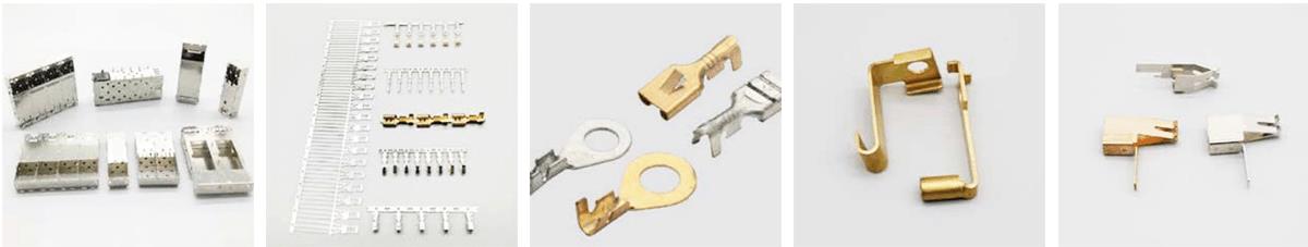
Metal stamping is a common manufacturing process, with stamped metal parts finding widespread applications across various industries. However, within the realm of metal stamping, there exists a notable distinction between ordinary metal stamping and precision metal stamping. In this article, we’ll delve into the nuances of precision metal stamping, its characteristics, advantages, applications, and considerations for choosing the right stamping process.
What is Ordinary Metal Stamping?
Ordinary metal stamping primarily involves relatively thick substrates without the need for intricate cutting, stretching, or other complex processes. Furthermore, the precision requirements for parts produced through ordinary metal stamping are not particularly high.
What is Precision Metal Stamping?
Precision metal stamping, on the other hand, demands meticulous attention to detail, incorporating a synergy of precise punching machines, materials, molds, lubricating oils, and advanced technologies. This method places a premium on achieving high levels of precision in the stamped parts, making it an ideal choice for applications where precision is paramount.
Applications of Precision Metal Stamping:
Automotive and Aerospace: Precision metal stamping plays a pivotal role in manufacturing parts for the automotive and aerospace industries. These parts must meet stringent standards, making precision stamping a necessity.
Electronics Industry: The electronics sector relies on precision metal stamping to produce intricate components such as sockets, circuit breakers, and fuse boxes.
Medical: Precision metal stamping proves invaluable in creating medical components, including temperature probes and surgical equipment.
Renewable Energy: This process finds application in renewable energy sectors, contributing to the production of components for solar panels and related equipment.
Specialized Parts: Precision metal stamping is ideal for crafting complex or highly specialized items across various industries.
Choosing Between Ordinary and Precision Metal Stamping:
The choice between ordinary and precision metal stamping hinges on the precision requirements and production volume:
For high-precision parts in large quantities: Opt for precision metal stamping.
For low-precision parts: Ordinary metal stamping is a suitable choice.
Characteristics of Precision Metal Stamping:
Strict Tolerance Requirements: Precision metal stamping demands strict tolerance adherence, showcasing an exceptionally high level of precision.
Flexibility and Adaptability: This method exhibits robust flexibility and adaptability, making it ideal for mass production.
Complex and Tiny Part Production: Precision metal stamping excels in creating intricate, small parts, particularly suited for the aerospace industry.
Computer-Aided Simulation: Before embarking on precision metal stamping operations, computer modeling simulations are often employed to identify errors or defects. This significantly reduces the likelihood of errors during the actual process.
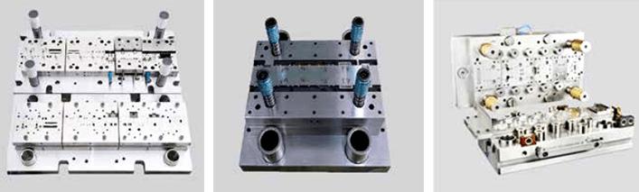
High-Quality Mold: Precision metal stamping relies on molds with outstanding wear resistance, ductility, fatigue resistance, and high-temperature resistance.
High-Precision Equipment and Materials: Utilizing high-precision machines and materials is crucial to achieving the desired results in precision metal stamping.
Requirements for Precision Metal Stamping Dies:
High Strength and Wear Resistance: Precision metal stamping dies must possess high strength and exceptional wear resistance to withstand the rigors of the metal stamping process.
Ductility: Ductility is critical to prevent brittle fracture during mold operation.
High Temperature Resistance: The dies should exhibit good high-temperature resistance to maintain strength and hardness when exposed to elevated temperatures.
Anti-Fatigue Properties: To withstand long-term cyclic pressure, precision metal stamping dies must have excellent fatigue resistance.
If you require precision metal stamping parts, KENENG is a reliable source for your needs. Their expertise spans various components, from stamping dies to precision connectors, metal clips, brackets, screws, springs, and more. With their extensive experience in the hardware industry, KENENG offers mature stamping production processes and a dedicated team. Simply reach out with your requirements, and they’ll provide you with a tailored, cost-effective solution. Welcome customers from all corners to inquire and collaborate with them at your convenience.
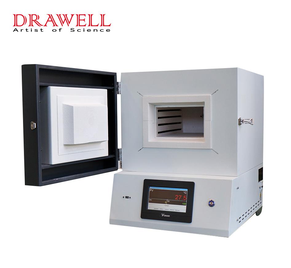
Muffle furnaces, known for their high-temperature heating capabilities, are indispensable tools in laboratories, catering to a wide range of applications. However, it’s essential to use these furnaces correctly to prevent harm and ensure the safety of both operators and equipment. This article provides valuable insights into the structure, operation, and precautions associated with muffle furnaces.
Understanding the Structure of Muffle Furnaces
Muffle furnaces are typically box-shaped, designed for heating, heat preservation, and cooling processes. They feature a single door or slot for feeding and discharging materials, making them easy to operate and maintain.
The furnace itself is constructed with a stainless steel plate and includes a heating and hot air circulation chamber. This design allows for improved temperature uniformity within the furnace, making it ideal for a wide range of heat treatment processes.
The separation of the furnace chamber and frame is a notable feature, with the chamber placed on load-bearing rollers at the bottom of the frame. This design enables free movement along the length direction during heating, ensuring even heat distribution.
To prevent hot gas leakage from the furnace, there are two layers of seals at the furnace door. The inner seal consists of a ceramic fiber rope, while the outer seal employs a silicone rubber sealing ring. To extend the seals’ lifespan, a stainless steel cooling water jacket is integrated into the furnace door seal for cooling. The door lock mechanism features a multi-point handwheel rotation locking system, providing uniform locking around the door. Additionally, a furnace door fixing device is installed on the furnace chamber’s end face, utilizing a movable double-hinge mechanism to move seamlessly with the furnace’s extension, thereby enhancing the sealing effect.
How to Operate a Muffle Furnace
Initial Inspection:
When your muffle furnace arrives, conduct a thorough inspection to check for any damage and ensure all accessories are present. The furnace typically requires no special installation and can be placed on a flat, stable surface. Keep the controller away from vibration and avoid placing it too close to the furnace to prevent overheating of internal components. Thermocouple Placement:
Insert a thermocouple into the furnace, ensuring it extends 20-50mm into the chamber. Fill any gap around the hole with asbestos rope. Ideally, use a compensation wire to connect the thermocouple to the controller, taking care to observe the correct polarity.
Safety Precautions:
Install a power switch at the power line’s inlet to control the main power supply. Proper grounding of the electric furnace and controller is crucial for safe operation. Temperature Indicator Calibration:
Before use, calibrate the thermometer indicator to zero. If using a compensating wire and cold end compensator, adjust the mechanical zero point to match the cold end compensator’s reference temperature. Without a compensating wire, adjust the mechanical zero point to the zero scale, noting that the indicated temperature represents the temperature difference between the measuring point and the thermocouple’s cold end. Initial Heating:
After confirming the correct wiring and calibration, cover the controller housing. Adjust the temperature indicator’s setting pointer to the desired operating temperature, and then power on the furnace using the power switch. The green light on the temperature indicator should illuminate, and the relay will start working. The ammeter will display the current, and as the furnace’s internal temperature rises, the temperature indicator’s pointer will gradually ascend. The green light indicates the temperature is rising, while the red light signifies the furnace is at a constant temperature.
Precautions for Muffle Furnace Operation
Stable Placement:
Always place the muffle furnace on a stable cement platform, with appropriate plugs, sockets, and fuses. Ensure proper grounding to avoid potential hazards. Safe Environment:
The working environment should be free of flammable substances, explosive materials, and corrosive gases. Avoid baking liquid samples like water and oil directly, and refrain from pouring various liquids or molten metals into the furnace to maintain cleanliness. Temperature Limits:
Do not exceed the furnace chamber’s maximum temperature, and avoid prolonged operation at the rated temperature. During operation, remain present and vigilant to any temperature fluctuations. If abnormalities occur, immediately disconnect the power and seek professional maintenance. Gentle Handling:
Close the furnace door gently to prevent damage to the furnace components. When handling samples, use a crucible clamp with care to avoid damage to the furnace chamber. Avoid Opening at High Temperatures:
Do not open the furnace door when the temperature exceeds 600°C. Wait for the furnace to naturally cool down before accessing the interior. Safety during Sample Handling:
After an experiment, remove the sample from heating and turn off the power supply. When placing a sample into the muffle furnace, slightly open the furnace door and wait for the sample to cool before carefully securing it to prevent burns.
Prevent Moisture Damage:
When not in use, disconnect the power supply and close the furnace door to prevent moisture from eroding the refractory components.
By following these guidelines and adhering to safety precautions, you can effectively and safely operate a muffle furnace, whether in a laboratory, industrial setting, or any other application requiring high-temperature heating. Proper handling and maintenance will ensure the longevity and reliability of your muffle furnace.
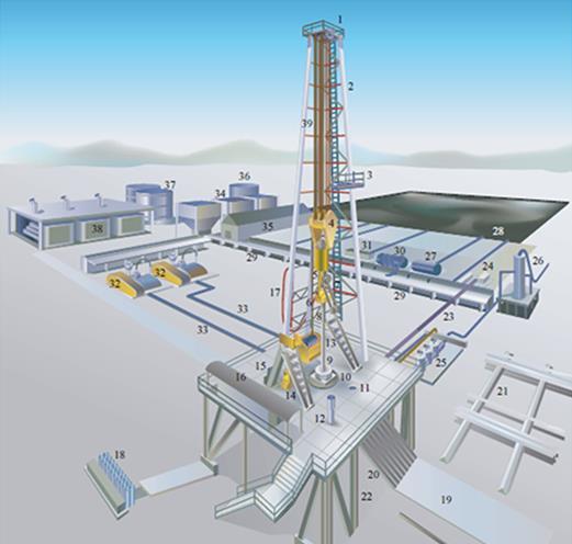
The oil and gas industry, a vast and intricate realm, relies on a symphony of engineering marvels to explore and extract hydrocarbons from beneath the Earth’s surface. At the heart of this intricate choreography is the drilling system, a complex ensemble of technologies, equipment, and methodologies that pierce through layers of rock and sediment to unlock the world’s energy resources. In this article, we delve into the world of drilling systems that are propelling the oil and gas industry into a new era of efficiency, safety, and resource optimization.
The Essence of Drilling Systems:
Drilling systems are the lifeblood of the oil and gas industry, facilitating the exploration and extraction of Earth’s hidden treasures. These intricate systems amalgamate cutting-edge technologies, machinery, and expertise to delve into the depths of the subsurface, unlocking coveted hydrocarbon reservoirs.
These systems orchestrate a synchronized dance of drill bits, drill strings, hoisting mechanisms, and mud circulation, culminating in the creation of wellbores. This intricate choreography not only grants access to precious resources but also embodies precision, innovation, and unwavering determination. Through the interplay of components like well control equipment, casing, and logging tools, drilling systems ensure operational integrity while guarding against potential hazards, all while harnessing the power of modern engineering.
As the industry evolves, drilling systems continue to be the backbone of oil and gas endeavors, embodying the relentless pursuit of energy excellence while reshaping the global energy landscape.
The Core Components of Drilling Systems:
The core components of drilling systems form an intricate web of technologies and equipment essential for the successful exploration and extraction of oil and gas resources. These components collaborate seamlessly to drive the drilling process forward, ensuring efficiency, safety, and optimal wellbore creation.
Drill Bit: The drill bit serves as the point of contact between the rig and the Earth’s crust. Innovative drill bit designs, such as polycrystalline diamond compact (PDC) and roller cone bits, are engineered to cut through various rock formations with precision.
Drill String: Comprising the drill pipe, drill collars, and other accessories, the drill string provides the conduit for transmitting power and torque from the rig to the drill bit.
Mud Circulation System: This system involves drilling fluid, often referred to as “mud,” which serves to lubricate the drill bit, cool the drill string, and carry cuttings to the surface. Mud also provides crucial pressure control to prevent blowouts.
Hoisting System: The hoisting system employs the drawworks to raise and lower the drill string, enabling vertical movement within the wellbore.
Rotating System: The rotating system powers the rotation of the drill string and bit, allowing for efficient drilling of the wellbore.
Together, these core components harmonize their functions, creating a symphony of engineering prowess that characterizes drilling systems in the oil and gas industry.
Benefits and Impact of Drilling Systems:
Efficiency Enhancement: Modern drilling systems optimize drilling speed, reduce non-productive time, and minimize downtime, contributing to more efficient operations.
Safety Advancements: Drilling systems incorporate state-of-the-art safety features, real-time monitoring, and automated controls to enhance personnel safety and prevent accidents.
Resource Optimization: By maximizing equipment utilization and minimizing operational inefficiencies, drilling systems contribute to cost savings and resource optimization.
Environmental Considerations: Advanced drilling technologies aim to minimize environmental impact through reduced emissions, efficient mud management, and optimized wellbore integrity.
Simulation of Drilling Systems:
In the dynamic realm of oil and gas exploration, the pursuit of efficiency, safety, and precision has spurred the evolution of drilling systems. Leading this transformation is simulation technology, an innovative approach that empowers the industry to test, optimize, and revolutionize drilling operations in virtual environments. Drilling systems simulations bring together the intricacies of engineering, data analysis, and real-world scenarios to create a digital playground for engineers, operators, and decision-makers.
To provide an authentic experience of oil drilling and equip students with relevant knowledge and skills, Esimtech has developed a drilling and well control simulation system. This system faithfully reproduces the working atmosphere of oil drilling operations. Through this simulation technology, individuals can gain a comprehensive understanding of the drilling system and master its application.
Innovations and Transformation in Drilling Systems:
In the ever-evolving landscape of the oil and gas industry, innovation stands as the driving force behind the transformation of drilling systems. Pioneering technologies are reshaping conventional practices, enhancing efficiency, safety, and environmental responsibility. These innovations are not only propelling the industry forward but also redefining its capabilities and potential.
Automated Drilling: Automation has revolutionized drilling operations by enabling real-time monitoring, data analysis, and decision-making. Automated drilling systems utilize sensors and advanced algorithms to optimize drilling parameters, detect anomalies, and adjust operations in response to changing downhole conditions.
Directional Drilling: Advanced directional drilling techniques, such as rotary steerable systems and electromagnetic guidance, enable precise wellbore placement and access to previously inaccessible reservoirs, maximizing resource recovery and reservoir drainage.
Managed Pressure Drilling (MPD): MPD techniques control wellbore pressure to prevent kicks and losses, enhancing safety and efficiency. By optimizing pressure, MPD enables drilling through challenging formations while minimizing formation damage.
Dual Gradient Drilling: This technique uses two different types of drilling fluid to balance wellbore pressures, making drilling in challenging environments, such as deepwater, more manageable.
Casing While Drilling (CWD): CWD systems allow operators to simultaneously drill and install casing, saving time and reducing the risk of wellbore instability.
These innovations are ushering in a new era of drilling systems, where precision, automation, and sustainability converge to unlock previously untapped potential in the oil and gas industry. As technology continues to advance, the industry is poised to reach greater depths, access more challenging reservoirs, and conduct operations with unprecedented efficiency and environmental responsibility.
Conclusion:
Drilling systems represent the dynamic heart of the oil and gas industry, combining cutting-edge technology, engineering prowess, and operational expertise to unlock vital energy resources.
Simulation-driven drilling systems have emerged as a game-changing force in the oil and gas industry, offering a virtual canvas for exploration and innovation. As this technology continues to evolve, the realm of drilling systems simulation promises to usher in a new era of efficiency, safety, and sustainability, shaping the future of oil and gas exploration and production.
The laboratory electronic analytical balance stands as an indispensable weighing instrument within laboratory settings. Its presence is not merely recommended but required for precise measurements and experiments. In the realm of electronic laboratory balances, the key to assessing their quality lies in their performance. Although some might argue against the relevance of four fundamental measurement criteria in evaluating electronic laboratory balances, the author maintains that these four parameters remain foundational for assessing their quality.
Stability of the Balance:
The stability of a balance signifies its ability to return to its initial equilibrium position after being subjected to disturbances. In electronic balances, this equilibrium is reflected in the analog or digital indication value. A stable electronic balance will always return to its initial indicated value after momentary disruptions. Without this stability, an electronic balance is practically unusable.
Balance Sensitivity:
Balance sensitivity pertains to the balance’s capability to detect changes in the mass placed on the weighing pan. In the context of electronic laboratory balances, this sensitivity is typically measured using graduation sensitivity or digital (division) sensitivity. The higher the sensitivity, the better the balance can detect even minuscule changes in mass. Sensitivity is, therefore, a critical factor in evaluating the quality of electronic laboratory balances.
Correctness of the Balance:
Correctness refers to the accuracy of the balance’s indication in relation to the true value. This accuracy can be assessed by examining the systematic error in the balance indication. For electronic balances, correctness is not only seen in the balance arm ratio for lever electronic laboratory balances but also in the analog or digital scale indications when loads are placed at various points on the balance plate. Correctness remains a significant parameter for assessing balance quality, whether it’s mechanical or electronic.
Invariance of Balance Indication:
The invariance of balance indication relates to the consistency of measurement results obtained when the balance measures the same object multiple times under identical conditions. This aspect includes controlling the repeatability, reproducibility, zero position, and return of the electronic balance, as well as monitoring drift in the balance indication value after an extended period of loading.
Selecting an Electronic Analytical Balance:
When purchasing electronic laboratory balances, it’s crucial for users to choose a balance that aligns with their weighing accuracy and range requirements. Here are some considerations for making the right choice:
Balance Accuracy: Ensure the balance accuracy matches your measurement requirements. Avoid overinvestment in accuracy that exceeds your needs. Consider the typical sample weights you work with, which should account for 60-80% of the balance’s weighing range.
Usage Occasions: Select balances that suit the environmental conditions in your lab. High-grade balances are suitable for controlled environments, while simple, rugged balances are better for outdoor or challenging conditions.
Quality Assurance and Additional Functions: Prioritize trusted quality assurance and consider additional features that might facilitate your experiments.
Cost-Effectiveness: Strive for a balance between quality and price. Seek products that offer the best cost-performance ratio, ensuring efficiency in resource utilization.
Annual Usage Costs: Consider the long-term costs, including maintenance and replacement expenses. A more expensive, durable balance might prove more cost-effective over time.
Compatibility and Tolerance: Evaluate how well the balance accommodates different operators and environmental factors, offering consistent and reliable results.
After-Sales Service: Choose products from reputable manufacturers with good after-sales support and the potential for function expansion.
Humanized Design: Opt for balances with user-friendly designs that minimize the risk of operational errors and offer a comfortable user experience.
In conclusion, the selection of an electronic analytical balance is a critical decision that can significantly impact the accuracy and efficiency of laboratory work. By considering these factors, users can make informed choices that align with their specific needs and laboratory conditions.