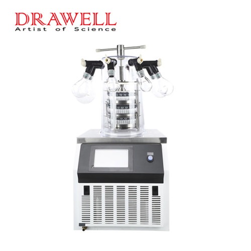
Innovative Solutions and Best Practices to Overcome the Challenges of Web Tension Control

Web tension control is indispensable in numerous industries, including printing, packaging, paper manufacturing, and textile production, where continuous materials or “webs” are processed. Ensuring optimal web tension is vital for product quality and manufacturing efficiency. However, web tension control presents its fair share of challenges that require innovative solutions. In this article, we will delve into these common challenges of web tension control and explore strategies to overcome them.

tension control

Common Challenges in Web Tension Control

1. Variability in Web Material Properties

Web materials often exhibit variations in thickness, width, and stretchability. These differences can make it challenging to maintain precise tension control. For instance, sections with varying thickness may require different tension levels.

2. Dynamic Changes in Speed

Web speeds can fluctuate in manufacturing processes due to accelerations and decelerations. These speed changes can affect web tension and, if not managed properly, lead to web breaks or low-quality output.

3. Web Wrinkling and Folding

Web tension controller must prevent web wrinkling or folding, which can damage materials and disrupt manufacturing. Wrinkles may result from issues such as misaligned rollers or inadequate web spreading.

4. Slippage and Snagging

Slippage between the web and rollers can result in inconsistent tension control, while web snagging or jamming can halt production and damage the material.

5. Environmental Factors

Environmental conditions like temperature and humidity can impact web tension control. Changes in these conditions may cause the web material to expand or contract, affecting tension.

6. Complex Web Paths

In certain processes, web materials follow intricate paths with multiple rollers and turns, making precise tension control challenging.

web tension controller

Strategies to Overcome Web Tension Control Challenges

Variability in Web Material Properties

Web Inspection: Regularly inspect the web material for variations in thickness, width, or stretchability, using web inspection vision systems to identify and classify variances.

Tension Compensation: Use tension zones or dancer rollers that can respond to material changes, allowing you to adjust tension control parameters for different sections of the web.

Dynamic Changes in Speed

Closed-Loop Control: Invest in closed-loop tension control systems that can react to changes in web speed in real-time. These systems use sensors to detect fluctuations and adjust tension accordingly.

Web Wrinkling and Folding

Proper Roller Alignment: Ensure rollers are precisely positioned and parallel to the web path to prevent wrinkles. Roller guides and edge sensors can help maintain alignment.

Web Spreading: Use web spreading devices or air bars to keep the web flat and wrinkle-free, aiding in the even distribution of strain across the web.

Advanced Control Algorithms: Employ tension control systems with advanced control algorithms capable of detecting and correcting wrinkles as they occur.

Slippage and Snagging

Surface Properties: Choose rollers with appropriate surface properties, such as coatings or grips, to minimize slippage. Ensure that rollers and guides are kept clean and well-maintained to prevent snags.

Environmental Factors

Controlled Environment: Manage temperature and humidity in the manufacturing area to maintain a controlled environment. Use sensors to monitor environmental conditions and adjust tension control systems accordingly.

Complex Web Paths

Accurate Alignment: Pay close attention to roller alignment in complex web paths. Implement tension zones at key points to manage tension more effectively.

Customized Tension Zones: Design tension zones tailored to the specific requirements of complex web paths. Tension control systems should be adaptable and configurable to meet unique process needs.

Additional Best Practices

Regular Maintenance: Implement routine maintenance to ensure that all tension control components, including rollers, sensors, and control systems, are in good working order.

Operator Training: Provide comprehensive training to operators and technicians to equip them with the knowledge to manage web tension effectively.

Data Analysis: Use data logging and analysis tools to track tension fluctuations and identify patterns or trends, aiding in the identification of the root causes of tension issues.

Continuous Improvement: Foster a culture of continuous improvement by seeking feedback from operators and engineers to refine tension control processes and systems.

Conclusion

The importance of web tension control cannot be overstated in industries relying on continuous web materials. By addressing the challenges of maintaining precise web tension through innovative solutions and best practices, manufacturers can ensure product quality, enhance process efficiency, and minimize downtime. Employing modern tension control technologies, implementing rigorous quality control procedures, and understanding the dynamics of web materials are key to achieving optimal outcomes in production processes.

An Article to Know Bolt Thread Standards in the Aerospace Industry Quickly

Aerospace bolts play a vital role in transferring shear and tensile loads, finding extensive application in areas that bear heavy concentrated loads or require disassembly within the realm of aviation. In this article, we explore the standards governing bolt threads in the aerospace industry, offering insights into the various specifications, fit quality, and identification symbols. These standards provide essential guidelines for selecting the right bolts for aviation applications.

1. Standards for Bolt Threads

In the aerospace industry, the standards for bolt threads are critical for ensuring the safety and integrity of aircraft structures. There are several key standards to consider:

a. American National Coarse Threads

b. American National Fine Threads

c. American Standard United Coarse Threads

d. American Standard United Fine Threads

These standards differentiate primarily based on two key factors:

1. Thread Pitch: Coarse and fine series threads of the same size share the same nominal thread diameter but differ in the number of threads per inch.

2. Tolerance Distribution: Each standard has distinct tolerance specifications for threads with a one-inch diameter. For instance, NF regulation utilizes 14 teeth per inch, represented as 1-14NF, while UNF regulation employs 12 teeth per inch, represented as 1-12UNF.

2. Fit Quality

The grade of a thread indicates the tightness of the fit between threaded parts, and it ranges from Grade 1 to Grade 5:

a. Grade 1 (Loose Fit): This level of fit allows for easy manual turning of the nut.

b. Grade 2 (Free Fit): Typically used for aerospace screws due to its specific requirements.

c. Grade 3 (Medium Fit): Commonly used for aerospace bolts where a secure yet manageable fit is essential.

d. Grade 4 and 5 (Tight Fit): These grades require a wrench for nut tightening. A higher grade corresponds to a tighter fit.

3. Identification Symbols

Bolt identification includes details such as diameter, length, and material. The unit of measurement for diameter is 1/16 inch, while the unit for bolt rod length is 1/8 inch. Material specifications are conveyed using English letters or symbols:

“C” denotes stainless steel.

“DD” signifies 2024 aluminum alloy.

“-” is used for nickel alloy steel.

General Standard Bolts in the Aerospace Industry

Hexagonal Head Bolt

The hexagonal head bolt is a widely used standard aviation bolt suitable for aircraft structure assembly, capable of withstanding tensile and shear loads. It adheres to the AN model specification standard and employs fine threads. Materials include chrome-plated nickel steel, stainless steel, and 2024 aluminum alloy.

Hexagon flange bolts supplier

Model Specification Code:

Example: AN 3 DD 14A

“AN” represents the standard bolt of USAF Navy specification.

“3” denotes a bolt diameter of 3/16 inch.

“DD” indicates the use of 2024 aluminum alloy.

“14” signifies a rod length of 1.5 inches.

“A” indicates the absence of a safety hole at the screw tail.

Engine Bolts Drilled in the Head

These bolts, identified by model specification codes ranging from AN73 to AN81 and MS20073 to MS20074, have slightly thicker heads with a through hole for a fuse. They possess the same tensile and shear strength as ordinary bolts.

Hexagon Socket Head Bolt

These bolts, bearing model specification codes MS20004 to MS20024, come in various diameters from 4/16 inch to 24/16 inch. They are made of high-strength steel and are not interchangeable with AN series hexagon bolts. These bolts are primarily used for connecting parts that bear both tensile and shear combined stresses.

For steel parts, the installation hole should be chamfered to allow the fillet to sink into the hole.

When installing on aluminum alloy parts, an MS20002C washer should be used beneath the bolt head.

Slotted Cheese Head Bolt

Slotted cheese head bolts are identified by model specification codes like AN21, AN22, and AN23, where the digits represent thread sizes (e.g., “6-40,” “8-36,” “10-32”). These bolts have fine threads (NF) and are ideal for bearing shear loads, often used as hinge pivot pins in rotating parts.

slotted cheese head screw

In Conclusion

Understanding the standards for bolt threads in the aerospace industry is crucial for selecting the right fasteners for aviation applications. The specifications, fit quality, and identification symbols of these bolts ensure the safety and reliability of aerospace structures. Proper bolt selection is an essential aspect of aviation engineering, contributing to the overall safety and performance of aircraft.

The Full-Size Snubbing Simulator: Why It is Important for Advancing Well Intervention Practices

Snubbing operations play a crucial role in well interventions by facilitating the controlled insertion and extraction of coiled tubing or jointed pipe into live wells. Ensuring the efficiency and safety of these operations requires well-trained operators with finely honed skills. To meet this need, the full-size snubbing simulator has emerged as a groundbreaking technology, offering snubbing operators an immersive and realistic training environment. In this article, we will explore the significance of the full-size snubbing simulator and its profound impact on the evolution of well intervention practices in the oil and gas industry.

full size snubbing simulator

Unveiling the Full-Size Snubbing Simulator

The full-size snubbing simulator stands as an innovative training tool designed to replicate real-world snubbing operations within a safe and immersive setting. Employing state-of-the-art technology such as virtual reality, physics-based modeling, and interactive simulations, this simulator provides operators with a hands-on, lifelike learning experience for snubbing operations.

At its core, the full-size snubbing simulator aims to enhance snubbing operator training and skill development. It meticulously mimics the configuration of snubbing units, control panels, downhole tools, and well conditions, allowing operators to interact with physical replicas of equipment and engage in various snubbing procedures in a controlled environment. This replication extends to the functionality, responses, and limitations of the actual equipment, providing operators with invaluable familiarity with their tools.

Transforming Well Intervention in the Oil and Gas Industry

The adoption of the full-size snubbing simulator promises to revolutionize well intervention practices across various dimensions in the oil and gas industry.

1. Enhancing Safety

Safety is paramount in the oil and gas industry, particularly during well intervention procedures. The full-size snubbing simulator offers a secure and controlled learning environment where operators can practice their skills without exposure to the inherent dangers of real field operations. This training equips operators to confidently manage real-world situations safely and effectively.

2. Skill Development and Proficiency

The simulator fosters muscle memory and the mastery of skills in a realistic environment, promoting hands-on learning. Operators can enhance their competency, efficiency, and decision-making abilities by engaging in a range of snubbing interventions. This, in turn, leads to more successful well interventions, reduced downtime, and optimized well productivity.

3. Cost-Effective Training

Traditional live field training for snubbing operations can be both costly and time-consuming. The Full-Size Snubbing Simulator eliminates the need for physical installations and lowers operational costs, offering a cost-effective alternative. Companies can streamline their training programs and resource management, resulting in substantial cost savings.

4. Customization and Versatility

The full-size snubbing simulator’s adaptability allows operators to create training scenarios tailored to specific well conditions and intervention challenges. This versatility ensures that operators receive specialized and comprehensive training, enabling them to effectively address a wide range of real-world snubbing situations.

snubbing simulator training room

5. Improving Operational Efficiency

When skilled operators are trained using the Full-Size Snubbing Simulator, snubbing operations become more efficient and precise. Optimized well interventions lead to increased well production, reduced downtime, and enhanced reservoir performance, ultimately improving overall operational efficiency and the industry’s success.

6. Accelerated Learning and Continuous Improvement

The simulator facilitates repetitive practice and ongoing skill development. Operators can run simulations repeatedly, learning from their mistakes and continuously improving their skills and strategies. This fosters a culture of learning and ongoing growth, ensuring that operators remain updated on industry best practices and technological advancements.

7. Technological Advancements and Innovation

The adoption of the full-size snubbing simulator underscores the industry’s commitment to embracing cutting-edge technologies. As the simulator evolves, incorporating advancements like virtual reality, artificial intelligence, and data analytics, it propels the industry toward more advanced and innovative well intervention techniques.

In Conclusion

The full-size snubbing simulator stands as a transformative tool, revolutionizing snubbing operator training and skill development in the oil and gas industry. As the industry continues to embrace the latest technologies, the snubbing simulator is a crucial catalyst for optimizing snubbing operation techniques and elevating the overall performance of well interventions in the oil and gas sector.

What are Common Faults of Drug Melting Point Apparatus and How to Solve Them

The drug melting point apparatus is a game-changer in pharmaceutical research, seamlessly integrating cutting-edge temperature control and high-definition video camera technology. This innovative combination not only delivers precise, stable, and dependable test results but also offers users an exceptionally convenient testing experience. With high-definition video capabilities, users can effortlessly observe the entire sample melting process, facilitating accurate measurement of melting points and distances.

At its core, the drug melting point apparatus leverages capillary tubes specified in the Pharmacopoeia as sample tubes and utilizes the liquid temperature transfer method, controlled by a computer-driven system for precise temperature management. Its operation is marked by reliability, high-precision temperature control, accurate measurements, excellent reproducibility, and user-friendly operation, all in strict adherence to the instrument, utensil, and determination method standards for melting point determination.

melting point apparatus

Diagnosing Common Issues and Remedies for Drug Melting Point Apparatus

Absence of Readings in the Final Melting Temperature Display Window

Issue Description: The temperature continues to rise, but the ammeter fails to reach the full scale, rendering the attainment of the final fusion temperature impossible.

Analysis: This problem might arise due to the misplacement of the brass tube, blocking the light path, or issues with the light source, such as a broken bulb, incorrect light path alignment, light scattering, or inadequate light energy.

Solution: Adjust the light path to correct the issue.

Ammeter Fails to Reset to Zero After Capillary Insertion

After the drug melting point apparatus is inserted into the capillary, the ammeter should read zero due to the obstruction caused by the medicine in the capillary. When the medicine melts, light passes through the glass capillary, reaching the photocell. The photosensitive output current of the photocell leads to the final melting display and resets the ammeter from zero to full scale. If the ammeter does not reset to zero when the capillary is initially inserted, the device becomes unusable.

Potential Causes for Ammeter Not Resetting to Zero:

Foreign objects in the brass tube where the capillary is placed; remove foreign matter using a thin copper wire, typically caused by broken glass capillaries.

Inadequate resistance; adjust the zero setting using the knob.

Abnormal Temperature Increase After Initial Temperature Setting

Various factors can lead to abnormal temperature fluctuations after pressing the initial temperature setting button, including issues with the temperature sensing element, digital wheel for setting initial temperature, and circuit board components.

Blown Fuse

A blown fuse signifies excessive current flow, often the result of a circuit short-circuit. To rectify this, ensure the load resistance is normal, confirm there are no short circuits in the filter capacitor, and, if required, replace the rectifier diode of the heating circuit power supply with a component of identical parameters.

Anomalies in Measured Values

Anomalies in measured values can be addressed through calibration with standard samples and repeated adjustments. Often, this discrepancy arises when users employ a new capillary from a different batch.

Heating Table Fails to Heat

A non-heating heating table may result from a blown heating wire, fuse, or damaged SCR (Silicon Controlled Rectifier). In the event of a blown heating wire, it can be repaired by rewinding the wire with a 0.3 mm diameter nickel-chromium wire, inserting a 0.5 mm-thick mica paper in between. Alternatively, an electric iron core’s heating wire and insulating mica paper can be used. When the SCR is damaged, it must be replaced as it controls the heating current’s magnitude by varying the conduction angle.

In conclusion, through understanding advanced technology and thorough troubleshooting guidance of the melting point apparatus, enhance the accuracy and efficiency of drug melting point analysis, further advancing pharmaceutical research and development.

What are Inflatable Life Rafts: Everything You Need to Know

Inflatable life rafts hold a pivotal role in maritime safety, serving as vital equipment that has, over time, rescued numerous lives during emergencies at sea. Whether during disasters, accidents, or any situation demanding the urgent evacuation of a vessel, these versatile and buoyant devices offer a lifeline for those in need. This article delves into the significance, design, deployment, and maintenance of inflatable life rafts, underscoring their critical role in maritime safety.

self-inflating life raft

The Importance of Inflatable Life Rafts

In the unforgiving realm of the open sea, where conditions can swiftly shift and catch sailors off guard, having a reliable means of survival is of paramount importance. Inflatable life rafts serve as the ultimate safeguard, offering a safe refuge for mariners when their vessel is no longer seaworthy. These rafts are meticulously designed to keep occupants afloat, shielded from the elements, and visible to potential rescuers until help arrives.

Key Design Features of Inflatable Life Rafts

The effectiveness and safety of inflatable life rafts hinge on several critical design elements, each meticulously crafted to ensure the raft’s ability to provide a safe haven:

Buoyancy and Materials

Buoyancy: Inflatable life rafts are crafted to provide buoyancy, enabling them to remain afloat even in turbulent seas. Buoyancy is achieved through the use of buoyant materials and compartments.

Materials: The materials employed in the construction of life rafts are meticulously selected for their buoyancy and durability. Common materials include rubberized textiles and synthetics that resist water absorption.

Self-Inflation Mechanism

Automatic Inflation: Modern inflatable life rafts feature automatic inflation mechanisms. Devices like hydraulic release units (HRUs) or automatic inflation devices (AIDs) activate upon deployment in water. This rapid inflation, without the need for manual intervention, is crucial for swift deployment in emergencies.

Stability and Resistance to Capsizing

Stability: Life rafts are engineered to maintain stability in water, preventing tipping or capsizing even in rough seas. This stability is vital for occupant safety and comfort.

Ballast Bags: Some life rafts are equipped with ballast bags or pockets that enhance stability by adding weight to the raft’s bottom.

Shelter and Protection

Canopies or Covers: Inflatable life rafts typically feature canopies or covers to provide shelter from the elements. These protective coverings shield occupants from sun, rain, wind, and spray, mitigating exposure-related concerns.

Insulated Floors: Certain types of life rafts come with insulated floors that help minimize heat loss to the chilly water beneath, maintaining a comfortable temperature within the raft.

Safety Equipment

Safety Essentials: Inflatable life rafts are equipped with essential safety gear, including maneuvering paddles or oars, signaling devices like flares or lights for attracting attention, and first aid kits to address injuries.

Survival Instructions: Many life rafts have survival instructions printed on their inner walls, guiding occupants in the use of survival equipment and procedures.

Visibility and Rescue Aids

Reflective Materials: Reflective materials are often incorporated into the design to enhance the raft’s visibility, particularly at night or in low-light conditions.

Sea Anchor: Some life rafts include sea anchors, which serve to stabilize and orient the raft, making it easier for search and rescue teams to locate.

Occupant Capacity

Inflatable life rafts are constructed to accommodate a specific number of individuals, determined by factors such as size, buoyancy, and safety regulations.

Packaging and Deployment

Life rafts are often compactly packed to minimize space on vessels. They are designed for swift and efficient deployment during emergencies, minimizing delays.

emergency inflatable life raft

Deployment and Use of Inflatable Life Rafts

Proper deployment and usage of inflatable life rafts are crucial components of maritime safety. Knowing how to deploy and utilize these lifesaving devices correctly can make the difference between survival and catastrophe during a maritime crisis:

1. Recognize the Emergency: It is imperative to assess the severity of the situation and the need to abandon the vessel in the event of a maritime disaster, such as shipwrecks, collisions, or sinking.

2. Locate and Access the Life Raft: Inflatable life rafts are typically stored in designated locations on board vessels. Familiarizing oneself with their locations in advance is vital. Follow the vessel’s abandonment procedures and remove any securing straps or coverings to access the life raft.

3. Release Mechanism Activation: Depending on the type of life raft and the vessel’s equipment, activate the release mechanism to deploy the life raft. This mechanism may be activated manually or automatically upon submersion in water. Ensure it deploys accurately and swiftly.

4. Life Raft Inflation: If the life raft is equipped with an automatic inflation system, it will inflate rapidly upon deployment in the water. Verify that it inflates completely and correctly. In the case of manually inflatable life rafts, locate and use the inflation mechanism as instructed, typically involving pulling a cord or manually inflating a compressed gas cylinder.

5. Boarding the Life Raft: Exercise caution when approaching the inflatable life raft. Pay close attention to the raft’s stability to prevent capsizing or damage. Board the raft carefully to prevent overturning, maintaining a balanced distribution of weight within the raft.

6. Occupant Safety and Equipment: Once inside the life raft, account for all occupants and ensure they are securely seated. Familiarize yourself with the safety equipment available within the raft, such as paddles, flares, first aid kits, and other survival gear. Follow the provided instructions for utilizing safety equipment, using signaling devices to increase visibility to potential rescuers.

7. Maintain the Raft: Stay inside the life raft and refrain from re-entering the water unless directed by rescue personnel or under extreme circumstances. Utilize the canopy or cover to protect the raft from the elements.

8. Communication and Signaling: If communication devices such as radios or emergency beacons are available, use them to alert authorities or nearby vessels of your location. Periodically activate and monitor signaling devices like flares or lights to enhance visibility to potential rescuers.

9. Stay Calm and Await Rescue: In an emergency situation, maintaining composure is essential. Panic can lead to poor decision-making. Patiently await rescue while adhering to safety protocols, retaining hope and confidence in the rescue process.

10. Follow Rescue Procedures: Upon the arrival of rescue personnel or another vessel, cooperate fully with their instructions and procedures for a safe recovery.

Maintenance and Inspection of Inflatable Life Rafts

Regular maintenance and inspection are imperative to ensure the reliability of inflatable life rafts during emergencies:

Inspection Intervals: Life rafts should undergo routine inspections as per maritime regulations and the manufacturer’s recommendations. These inspections encompass checking for leaks, examining the inflating system, and verifying the operational status of all safety equipment.

Professional Servicing: Skilled specialists should service life rafts regularly. This entails inspections and rectification of any issues. Repacking the raft is often part of the servicing process to ensure proper inflation.

Conclusion

Inflatable life rafts represent indispensable safety assets on vessels of all types, serving as lifelines for mariners in times of emergency at sea. Their buoyancy and stability make them essential tools for survival and rescue. Proper maintenance and familiarity with deployment procedures are critical to ensuring that these lifesaving devices perform reliably when needed most.

Printing Inspection Systems: Revolutionizing Quality Control and Enhancing Efficiency in Various Industries

The role of printing inspection systems has transformed significantly from their initial application in the printing industry to becoming indispensable tools across a wide spectrum of industries. Originally designed to ensure print quality, detect imperfections, and maintain production standards within the printing industry, these systems have evolved over time. The adaptability, precision, and efficiency of printing inspection systems have led to their integration into a diverse range of industries, revolutionizing quality control and enhancing efficiency in various industrial manufacturing processes.

Web Video Inspection System for Printing

The Evolution of Printing Inspection Systems

The journey of printing inspection systems has seen remarkable advancements. These systems were initially deployed in printing presses to identify printing defects such as smudges, misalignment, or irregular colors. They played a crucial role in upholding the quality and uniformity of printed materials.

However, breakthroughs in technology, particularly in the fields of computer vision, artificial intelligence, and automation, have propelled these systems into versatile tools with broader applications. The evolution of printing inspection systems can be summarized as follows:

1. Enhanced Imaging Technology:

Modern printing inspection systems utilize high-resolution cameras and powerful image sensors capable of capturing even the minutest details and flaws with astonishing clarity. This level of precision equips them to detect imperfections in a wide array of materials.

2. Advanced Algorithms:

The incorporation of machine learning algorithms and artificial intelligence has significantly amplified the capabilities of these systems. They can now detect faults in real-time, classify anomalies, and respond to evolving production conditions.

3. Expanded Applications:

Printing inspection systems have transcended traditional printing processes. They are currently employed across various industries, including packaging, pharmaceuticals, electronics, automotive, textiles, and more. Their versatility and adaptability make them invaluable assets in diverse manufacturing contexts.

Applications Across Industries of Printing Inspection Systems

Packaging Industry:

Printing inspection systems are indispensable in ensuring the quality and accuracy of packaging materials. They can identify defects in labels, cartons, and flexible packaging, contributing to the prevention of packaging and labeling issues that might result in costly recalls.

Pharmaceutical Industry:

Precision and quality control are of paramount importance in pharmaceutical manufacturing. Printing inspection systems are deployed to verify the accuracy of printed information on drug labels and packaging, thus guaranteeing patient safety and regulatory compliance.

Electronics Industry:

In the electronics industry, the inspection of printed circuit boards (PCBs) for soldering, component placement, and trace continuity issues is critical to maintaining product quality.

Automotive Industry:

Printing inspection systems are instrumental in upholding the quality of printed materials used for labeling, instruction manuals, and decorative elements in the automotive sector. They play a crucial role in ensuring brand consistency and product quality.

Textile Industry:

In textile manufacturing, these systems are employed to assess color consistency, pattern alignment, and fabric print imperfections. They contribute to the production of high-quality fabrics utilized in fashion, home furnishings, and various applications.

Food and Beverage Industry:

Accurate labeling and packaging are essential in the food packaging sector to adhere to regulations and ensure consumer safety. Printing inspection systems play a pivotal role in verifying the accuracy of labels and packaging materials, reducing the likelihood of errors.

Aerospace Industry:

In the aerospace industry, precision and quality control are indispensable in the manufacturing processes. Critical printed components, such as circuitry on aerospace components and labels, undergo meticulous examination using printing inspection systems.

printing inspection machine

Benefits of Printing Inspection Systems Used in Various Industries

The widespread adoption of printing inspection systems across industries offers several key advantages:

1. Quality Assurance:

These systems enhance product quality by detecting defects early in the manufacturing process, reducing waste, and preventing substandard products from reaching consumers.

2. Cost Reduction:

By identifying defects and errors promptly, manufacturers can cut production costs related to rework, waste materials, and product recalls.

3. Efficiency:

Automated inspection processes improve production efficiency by providing real-time feedback and diminishing the need for manual inspections.

4. Compliance:

Printing inspection systems provide the accuracy and consistency needed by industries with stringent regulatory requirements, ensuring compliance with norms and regulations.

5. Brand Reputation:

Delivering high-quality products consistently helps build a positive brand reputation and fosters consumer trust.

Conclusion

Printing inspection systems have evolved from their origins in the printing industry to become versatile tools with diverse applications in various manufacturing sectors. The state-of-the-art imaging technologies, machine learning capabilities, and precision provided by printing inspection systems play a critical role in quality control, efficiency, and compliance. As technology continues to advance, we can anticipate printing inspection systems to have an even greater impact, contributing to higher quality and productivity in a variety of industries.

What are the Distinctions between CNC Machining and Stamping

Metal processing commonly utilizes two methods: stamping processing and CNC numerical control (CNC) machining. KENENG offers CNC machining, stamping, and injection molding services. This article aims to elucidate the distinctions between CNC machining and stamping, as well as how to differentiate between CNC machining and stamping parts.

Understanding the Definition Difference Between CNC Machining and Stamping:

Stamping Processing:

Stamping processing is a manufacturing technique that utilizes stamping equipment to apply direct deformation force to a sheet within a mold. This process results in parts with specific shapes, sizes, and performance characteristics.

CNC Machining:

CNC machining involves the production of parts with defined dimensions, shapes, and performance attributes through programming control using CNC machining language. It entails regulating the tool’s feed speed, spindle speed, tool changes, and various mechanical cutting processes, including turning, milling, planing, grinding, among others.

CNC lathe parts

Differences Between CNC Machining and Stamping:

Production Speed:

CNC machining is comparatively slower in production compared to stamping. When speed is the primary concern, stamping is the preferred choice.

Output:

Stamping is ideal for high-volume production, while CNC machining is more suitable for lower volume production.

precision metal stamping machine

Cost:

CNC machining is known for its precision but comes at a higher cost, whereas stamping is relatively cost-effective.

Production Accuracy:

Stamping struggles to achieve complex designs, while CNC machining exhibits higher precision and easily handles intricate designs.

Processing Characteristics:

Characteristics of CNC Machining:

Strong adaptability: CNC machines can process new workpieces with reprogrammed processing programs.

High processing precision: CNC machine tools work with precision, often achieving a pulse equivalent of 0.001mm.

Low labor intensity: CNC equipment carries out tasks automatically, reducing manual labor.

Good economic benefits: CNC machining delivers stable precision, minimizing waste, and ensuring economic efficiency.

Characteristics of Stamping Processing:

High production efficiency: Ordinary presses can perform numerous strokes per minute, achieving one stamping part per stroke.

Stable stamping quality: Molds ensure the size and shape accuracy of stamped parts, with long mold lifespans ensuring consistency.

High strength and rigidity in stamped parts.

Material-saving: metal stamping generates minimal waste and is an eco-friendly processing method.

Distinguishing Between CNC Machining Parts and Stamping Parts:

Stamping parts typically exhibit burrs at notches, leading to less smooth and flat surfaces that can potentially cause cuts when touched.

metal stamping connector

CNC machining parts, on the other hand, feature smooth and flat surfaces, promoting safety and tactile comfort.

This article outlines the disparities between CNC machining and stamping, along with variations in their resulting products. KENENG specializes in the sale and production of stamping dies and parts, as well as CNC numerical control processing products. These offerings are renowned for their cost-effectiveness and quality, and KENENG is committed to swift delivery and exceptional customer service.

Portable Workover Simulators: Revolutionizing Workover Operations

This article is aiming to introducing portable workover simulators which has transformed the way the oil and gas industry approaches workover operations, emphasizing the importance of highly qualified personnel and meticulous planning to ensure productivity and safety in the field. These portable simulators leverage cutting-edge software, hardware, and virtual reality technologies to create realistic and immersive training environments that can be deployed wherever workover activities are conducted. Let’s delve deeper into the core components and functions of these portable workover simulators.

Portable Workover Simulator

Key Components of Portable Workover Simulators

Portable Computer or Laptop: The primary hardware component of a portable workover simulator is a high-performance PC or laptop. It should feature a robust processor, ample memory, and a dedicated graphics card capable of rendering intricate simulations. Portability is a key feature, allowing the setup of the simulator at workover sites.

Virtual Reality (VR) or Augmented Reality (AR) Devices: Many workover simulations integrate VR or AR technologies to enhance the user experience. Headsets, goggles, or glasses create immersive visuals and provide a sense of presence within the virtual environment. These devices may also include hand controllers or other input mechanisms for users to interact with and perform tasks on the simulated equipment.

Haptic Feedback Devices: Haptic feedback devices offer tactile sensations to the user, heightening the realism of the simulation. Through vibrations or forces applied to the user’s hands or other body parts, these devices simulate the sensation of touch. For example, when handling virtual tools or equipment, haptic feedback can offer resistance or feedback, mimicking the physical sensations experienced during actual workover procedures.

Simulation Software: The heart of portable workover simulators is their simulation software. This oil and gas software is responsible for crafting the virtual environment, replicating the physics and mechanics of workover operations, and providing an interactive experience. It generates lifelike graphics, models fluid and equipment behaviors, and incorporates real-world data to faithfully represent well conditions and associated challenges.

Instructor station software-Drilling parameter setting

Data Integration and Analysis: Workover simulators rely heavily on simulation software to create the virtual world and provide a realistic experience. The software can integrate real-time data streams from the field, enhancing the simulation and offering valuable insights. This may include data on well parameters, production statistics, or equipment performance. By incorporating real-time data, the simulator can dynamically adjust the simulation based on changing conditions and provide operators with feedback and analysis of their actions and decisions.

User Interface and Controls: A user-friendly interface and intuitive controls ensure effective interaction with the simulator. Operators can navigate the virtual environment, control equipment, and make decisions through an interface that closely mirrors real-world workover operations.

Key Functionality of Portable Workover Simulators

Realistic Workover Environment: Portable workover simulators meticulously replicate the physical environment encountered during actual workover procedures. They model the wellbore, downhole equipment, and geological features of the workover site, providing a visually accurate representation. This realism aids workers in familiarizing themselves with the specific conditions they will face and enhances their understanding of the operational environment.

Interactive Training: Portable workover simulators encourage active participation in simulated workover processes, facilitating interactive training sessions. Users can manipulate virtual tools and equipment, execute tasks, and engage in various workover operations within the simulator. This hands-on approach aids workers in skill development, decision-making enhancement, and confidence building.

Scenario Customization: These simulators permit the customization of scenarios to match the specific well conditions and operational requirements of each site. Operators can input site-specific data, such as well parameters, production history, and equipment specifications, to create virtual well models closely mirroring the actual workover site. This customization allows personnel to learn and plan in an environment that accurately replicates their specific well’s characteristics.

Real-Time Feedback and Assessment: Portable workover simulators offer real-time feedback and assessment of user actions and performance. The simulator continuously monitors and evaluates user interactions and decisions, providing prompt feedback on technique, timing, and adherence to safety protocols. This real-time assessment allows workers to learn from their mistakes, adjust their techniques, and enhance their overall competence in workover operations.

Planning and Optimization: These simulators provide real-time workover planning and optimization capabilities. Operators can experiment with various workover strategies, identify potential risks, and refine their plans for increased efficiency. The simulator serves as a platform for operators to explore different scenarios, assess potential outcomes, and optimize workover operations, ultimately reducing operational risks.

Safety Protocol Training: Safety is paramount in workover operations, and portable simulators play a vital role in improving safety training. They offer a controlled environment for personnel to practice safety protocols, emergency procedures, and critical safety skills related to workover tasks. By simulating potential hazards and emergency scenarios, workers can acquire essential skills and reflexes for effective responses in real-life situations.

In summary, the introduction of portable workover simulators represents a significant advancement in the oil and gas industry, revolutionizing workover operations by enhancing training, safety, and operational efficiency. These portable devices provide a valuable tool for workforce development and preparation for real-world workover challenges.

Spray Dryers and Freeze Dryers: What are the Disparities and What are the Respective Advantages

Spray dryers and freeze dryers are both essential instruments in the world of substance drying, each with distinct applications and equipment features. This article aims to elucidate the disparities between spray dryers and freeze dryers and highlight their respective advantages.

Spray Drying

Spray drying is a systematic technology used for material drying. In this method, a liquid solution or emulsion is atomized within a drying chamber. As the fine mist of liquid encounters hot air, rapid water evaporation occurs, yielding a dry product. This process can directly transform solutions and emulsions into powders or granular products, eliminating the need for separate evaporation, crushing, and other processes.

The fundamental principle involves dispersing the material into ultra-fine particles resembling mist through mechanical means, thus increasing the water’s evaporation surface area and hastening the drying process. Most of the water is instantly removed upon contact with hot air, leaving the solid components dry in powder form.

the spray dryer

Spray drying operates at high temperatures, enabling swift moisture evaporation and producing a superior drying effect. Simultaneously, the resulting particles are relatively uniform in size and possess excellent flow properties.

This method is particularly beneficial for preserving the nutritional value of substances that are heat-sensitive. In cases where high temperatures are necessary to eliminate specific substances, such as trypsin inhibitors in soybeans, spray drying technology is an ideal choice. The process effectively converts liquids into powders while preserving the taste, color, and nutritional content of food, all while removing microbial contamination.

Apart from moisture removal, spray drying has various other applications, including altering substance size, shape, or density, facilitating ingredient addition in production processes, and aiding in the creation of products adhering to strict quality standards. Notably, fruit and vegetable powders produced via spray drying retain the nutritional content of fresh produce while reducing volume for convenient consumption and transportation.

For reference, here’s a nutritional comparison between fresh pumpkin and spray-dried pumpkin powder:

Drying technology varies between high-temperature and low-temperature drying. While spray drying employs high-temperature spraying, there are situations where low-temperature freeze-drying, or freeze drying, is a more appropriate choice.

Advantages of Freeze Drying

Freeze drying, also known as sublimation drying, involves freezing a water-containing material below its freezing point, turning the water into ice, and subsequently transforming the ice into vapor under a high vacuum to remove it. Materials can either be pre-frozen and then dried or frozen directly within the drying chamber under rapid evacuation. The water vapor resulting from sublimation is removed via a condenser, with the necessary heat for vaporization supplied through thermal radiation.

The fundamental principle of laboratory freeze dryer capitalizes on the three phases of water, where point O signifies the common point of all three phases and OA represents the melting point of ice. By reducing pressure below the triple point pressure (below 646.5Pa, at a temperature below 0°C), moisture in materials can directly transition from water to water vapor without passing through a liquid phase.

freeze dryers

By applying this principle, wet raw materials can be frozen below their freezing point, causing moisture to solidify into ice. In a suitable vacuum environment, this ice is then sublimated directly into vapor, with the water vapor being condensed by a condenser, thus achieving effective drying.

Freeze drying offers several advantages:

Suitability for Heat-Sensitive Substances: Operating at low temperatures makes freeze drying ideal for preserving the integrity of heat-sensitive materials such as proteins and microorganisms, ensuring they do not denature or lose biological activity.

Minimal Loss of Volatile Components: The low-temperature drying process minimizes the loss of volatile components in substances, making it suitable for drying chemical products, medicines, and food items.

Preservation of Original Properties: Freeze drying prevents the growth of microorganisms and the action of enzymes, allowing the original properties of substances to be maintained.

Maintenance of Original Structure: The frozen state preserves the substance’s volume and structure, preventing condensation and maintaining its original form.

Rapid Reconstitution: Freeze-dried substances, resembling sponges, dissolve quickly and revert to their original state when rehydrated.

Oxygen Protection: Drying under vacuum conditions minimizes oxygen exposure, preserving easily oxidized substances.

Long Shelf Life: Freeze drying removes over 95-99% of water, facilitating long-term storage without deterioration.

In summary, spray dryers and freeze dryers each possess unique strengths and drawbacks. Spray drying offers rapid moisture removal and uniform particle sizes but involves high temperatures. In contrast, freeze drying operates at low temperatures, preserving delicate substances, but the process can be time-consuming. The choice between the two depends on the specific needs of the application and the characteristics of the material being dried.

Why Choose Professional Laboratory Refrigerators

Laboratory refrigerators serve a crucial role in preserving vaccines, medicines, and chemical reagents. These sensitive materials demand precise temperature control, and as a result, laboratory refrigerators are essentially “incubators” with a narrow temperature range to meet these exacting requirements.

laboratory refrigerator

In stark contrast, household refrigerators are designed primarily for food storage and rely on direct cooling methods, combining both refrigeration and freezing compartments with a shared compressor. Household refrigerators have only one temperature controller, geared towards maintaining food freshness. Their temperature stability requirements are relatively lenient, resulting in potential issues such as temperature fluctuations and inconsistent internal temperatures.

Notably, reputable refrigerator manufacturers explicitly specify in household refrigerator manuals that these appliances are intended solely for storing food and are unsuitable for preserving blood products, medicines, biological materials, chemical reagents, technical documents, or similar non-food items.

Understanding the Hazards of Using Household Refrigerators in Laboratories

Despite these clear distinctions, some laboratories continue to employ household refrigerators for non-food storage. However, as GMP certification standards become increasingly stringent and inspections more rigorous, using household refrigerators for laboratory applications poses several critical risks. For instance:

Temperature Fluctuations: Household refrigerators lack real-time temperature monitoring and adjustment capabilities, potentially leading to temperature deviations that can damage sensitive items before corrective action is taken.

Temperature Inconsistency: Direct cooling in household refrigerators can result in uneven temperature distribution, with the upper regions being colder than the lower ones, posing a risk to stored materials.

Manual Temperature Recording: Laboratory personnel must manually record temperature data in household refrigerators, a process prone to inaccuracies, errors, and omissions, and ill-suited for long-term storage and analysis.

Lack of Performance Insights: Household refrigerators do not offer the tools necessary for intuitive equipment usage monitoring and analysis.

Explosion Hazard: Storing flammable and explosive chemical reagents in household refrigerators carries an inherent risk due to their design and cooling method.

Blood Bank Refrigerator

The Case for Professional Laboratory Refrigerators

Professional laboratory refrigerators offer a solution to these concerns. These refrigerators are typically single-refrigeration or single-freezing units, providing precise temperature control. They employ air-cooled refrigeration methods to maintain consistent internal temperatures throughout the refrigerator, ensuring the safety of stored materials.

Professional laboratory refrigerators come equipped with features such as temperature displays, data recording, and temperature alarms, meeting the strict requirements of GMP inspections. Specialized explosion-proof refrigerators are also available for storing flammable and explosive items, prioritizing safety for both personnel and the laboratory environment.

Introducing Drawell: A Leader in Laboratory Refrigeration

Drawell, a Chinese laboratory refrigerators manufacturer established in 1999, has been at the forefront of laboratory refrigeration technology. They are renowned for their innovative designs, technological breakthroughs, and a deep commitment to serving professional laboratories.

Their range of laboratory refrigerators includes:

-86℃ Laboratory Refrigerator: Available in vertical and horizontal configurations with capacities ranging from 58L to 838L, offering temperature ranges from -40℃ to -86℃.

4℃ Laboratory Refrigerator: Also known as the 4℃ Blood Bank Refrigerator, with an effective capacity of 500L and temperature range of 4±1°C, featuring an alarm system for added safety.

2-8℃ Laboratory Refrigerator: These high-precision refrigerators offer temperature ranges from 2 to 8℃, with capacities spanning 100L to 1500L and various refrigeration systems, including forced air cooling and auto defrost.

Drawell laboratory refrigeration ensure the safe storage of your valuable materials and compliance with the highest industry standards.

通过 WordPress.com 设计一个这样的站点
从这里开始