Remaining competitive in the ever-evolving manufacturing sector requires a proactive embrace of technological advancements that enhance precision, efficiency, and overall production quality. This case study examines the triumph of ABC Manufacturing, a forward-thinking industry player that significantly improved its production processes by adopting web guiding systems. This exploration delves into the challenges faced, the chosen solutions, and the tangible benefits realized.
Why ABC Manufacturing Opted for Web Guiding Systems
Background:
Specializing in flexible packaging materials for diverse industries such as food and beverage, pharmaceuticals, and consumer goods, ABC Manufacturing recognized the imperative to enhance the precision of its manufacturing processes, particularly web alignment, to meet growing demands for quality and efficiency.
Challenges Faced:
Inconsistent Web Alignment:
Dealing with issues related to inconsistent web alignment, ABC Manufacturing experienced product defects and increased waste due to manual adjustments causing production delays.
Downtime and Productivity Loss:
The manual alignment process led to frequent downtime, adversely impacting overall productivity. An automated solution was deemed necessary to minimize disruptions.
Quality Control Concerns:
Variations in web alignment raised quality control concerns in an industry where precision is paramount. ABC Manufacturing aimed for greater consistency to meet stringent quality standards.
Selected Solution: Web Guiding Systems Implementation
After a thorough evaluation of potential solutions, ABC Manufacturing decided to implement state-of-the-art web guiding systems tailored to the unique requirements of their production line.

How ABC Manufacturing Successfully Implemented Web Guiding Systems
Key Components of the Implemented Web Guiding System:
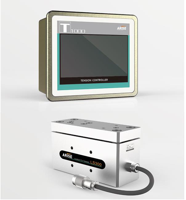
High-Resolution Optical Sensors:
Opting for web-guiding systems with high-resolution optical sensors provided precise real-time feedback on material position, ensuring accurate alignment.
Advanced Actuators:
The chosen systems featured advanced web guide actuators, combining servomotors and pneumatic cylinders for quick and precise adjustments to ensure optimal web alignment.
User-Friendly Controller with Programmability:
Integration with a programmable, user-friendly web guide controller allowed operators to set parameters, fine-tune adjustments, and adapt the system to various materials and production needs.

Steps for Successful Implementation:
Assessment of Requirements:
Conduct a thorough assessment of the manufacturing process to identify specific web guiding requirements, considering material type, width, and processing speed.
Selection of Appropriate System:
Choose a web guide system that aligns with identified requirements, considering sensor technology, controller capabilities, and compatibility with existing machinery.
Integration with Existing Equipment:
Ensure seamless integration with the existing production line, collaborating with the system provider to adapt the solution to the facility’s unique characteristics.
Operator Training:
Train operators on the proper use and maintenance of the web guiding system, familiarizing them with the user interface and troubleshooting procedures to minimize downtime.
Performance Monitoring:
Implement a monitoring system to track the performance of the web guiding system, regularly reviewing data to identify areas for optimization and preventive maintenance.
Continuous Improvement:
Embrace a culture of continuous improvement, regularly evaluating the system’s effectiveness and exploring opportunities for enhancements or upgrades.
Benefits of Successfully Implementing Web Guiding Systems at ABC Manufacturing
Precision and Consistency:
The implementation resulted in a significant improvement in web alignment precision, enhancing the consistency of the production line and reducing variations in the final product.
Dramatic Reduction in Waste:
ABC Manufacturing experienced a substantial reduction in material waste due to the automated adjustments provided by the web guiding system, aligning with the company’s commitment to sustainability.
Enhanced Productivity:
Virtually eliminating downtime from manual adjustments, the web guiding system significantly increased overall productivity, enabling ABC Manufacturing to meet production targets more efficiently.
Quality Assurance and Customer Satisfaction:
The increased precision directly influenced product quality, allowing ABC Manufacturing to confidently meet and exceed clients’ stringent quality standards, enhancing overall customer satisfaction.
Adaptability to Changing Requirements:
The web guiding system’s programmability enabled ABC Manufacturing to quickly adapt to changing production requirements, proving invaluable when dealing with a wide range of materials and product specifications.
Conclusion
The successful integration of web guiding systems showcases the transformative impact of advanced manufacturing technologies. By addressing issues of inconsistent web alignment, downtime, and quality control, ABC Manufacturing not only optimized its production processes but also established itself as a precision manufacturing leader. This case study underscores the importance of strategic technology adoption in remaining competitive and meeting the dynamic demands of the modern manufacturing landscape.