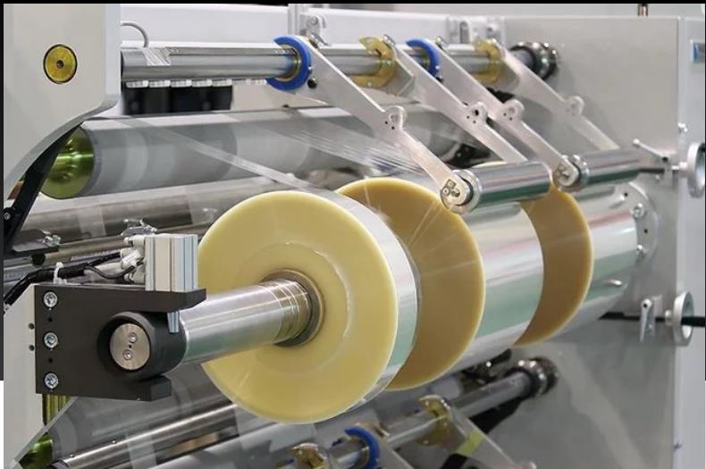
Precision and accuracy play pivotal roles in industrial manufacturing, particularly in operations involving continuous webs of materials like paper, film, or foil. Even minuscule variations can lead to costly faults and production delays. To ensure seamless operations and high-quality outputs, regular maintenance and calibration of web guiding systems are indispensable. In this article, we delve into the significance of maintenance and calibration practices in maximizing the efficiency and reliability of web guiding systems.

Regular Maintenance Practices in Web Guiding Systems
Cleaning and Inspection: Regular cleaning and inspection are essential maintenance procedures for web guiding systems. Removing debris, dust, and residue from guiding rollers and sensors ensures smooth operation and longevity. Visual evaluation for wear, damage, or misalignment is crucial to preempt potential issues.
Lubrication: Proper lubrication of moving parts minimizes friction, wear, and ensures smooth functioning. Following manufacturer recommendations for lubrication type and frequency is paramount to extend component life and maximize system operation.
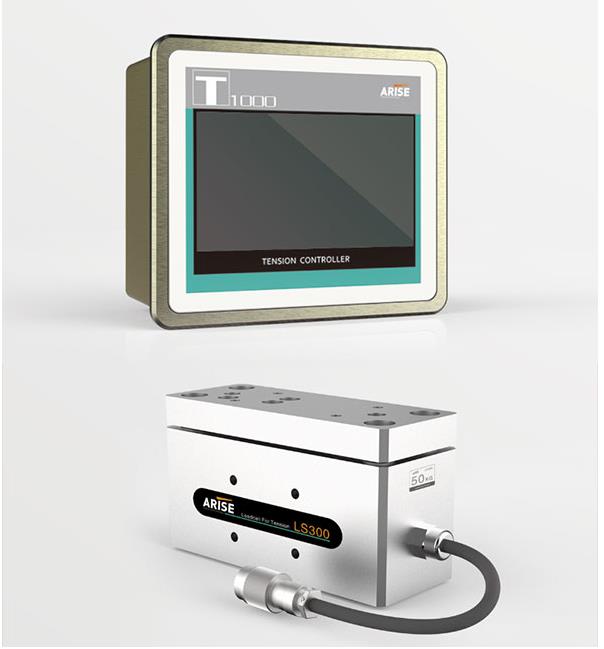
Tension Adjustment: Maintaining proper web tension is vital to prevent wrinkles, creases, and breaks. Regularly checking and adjusting tension settings ensures consistent tension levels across the web, enhancing product quality and process efficiency.
Alignment Verification: Regularly verifying the alignment of guiding rollers and sensors guarantees precise web guidance. Proper alignment reduces edge deviations and maintains product quality. Utilizing alignment tools and techniques ensures accuracy.
Software Updates: Staying updated with the latest software releases provided by the manufacturer enhances system functionality and reliability. Prompt installation of updates ensures compatibility with other equipment and processes, benefiting from performance enhancements and bug fixes.

Calibration Practices in Web Guiding Systems
Sensor Alignment: Accurate sensor alignment is crucial for reliable web position detection. Ensuring sensors are perpendicular to the web path and aligned with the desired tracking position optimizes detection accuracy along the entire web width.
Tension Calibration: Proper tension calibration maintains consistent tension levels, minimizing faults and material waste. Monitoring tension levels and adjusting control systems according to production requirements and material properties is essential.
Position Control Adjustment: Calibrating position control settings minimizes edge deviations and maintains correct web alignment. Fine-tuning settings like gain, offset, and response time optimizes alignment accuracy.
Sensor Sensitivity Optimization: Optimizing sensor sensitivity ensures reliable detection of web deviations. Adjusting sensitivity settings based on material characteristics and environmental conditions enhances detection accuracy, even at low contrast or speed variations.
Verification and Validation: After calibration adjustments, conducting test runs using representative materials and conditions verifies system performance. Comparing actual performance against specified tolerances and making further adjustments ensures accuracy and reliability.
Documentation and Record-Keeping: Maintaining thorough records of calibration activities facilitates traceability and responsibility. Documenting calibration dates, adjustments, and test results aids in troubleshooting and continuous improvement efforts.
Conclusion
Regular maintenance and calibration are indispensable practices for ensuring the reliable web guiding systems with optimal performance. By following proactive maintenance schedules, conducting thorough inspections, and calibrating system parameters as needed, manufacturers can reduce downtime, eliminate defects, and increase production efficiency.