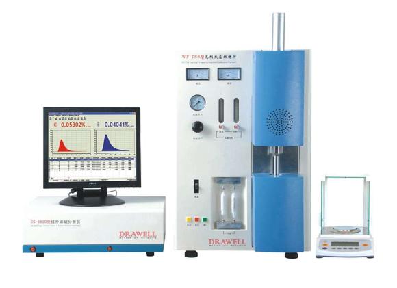
Analyzing carbon and sulfur content in various materials is critical across industries like steel, petroleum, environmental monitoring, and research. Carbon Sulfur Analyzers are specialized instruments facilitating accurate measurements, essential for quality control, process optimization, and regulatory compliance. This article explores the features and applications of Carbon Sulfur Analyzers, showcasing their significance in diverse industries.
Features of Carbon Sulfur Analyzers
Carbon Sulfur Analyzers may vary in features based on models and manufacturers, yet common attributes include:
High Sensitivity and Accuracy: Designed for precise carbon and sulfur measurement, these analyzers detect trace amounts of elements, ensuring accurate analysis results.
Wide Analytical Range: With a broad range, they analyze samples with varied carbon and sulfur concentrations, accommodating diverse sample types.
Rapid Analysis: Many offer fast analysis times, crucial for efficient sample throughput and productivity, especially in manufacturing and quality control.
Sample Flexibility: Capable of handling solids, liquids, and gases, these analyzers provide flexibility in sample size and form, facilitating analysis of a wide range of materials.
Automation and Software Integration: Advanced models automate sample handling, analysis, and data processing, reducing human error. Integration with software platforms enhances data management and analysis efficiency.
Steel and Metal Industry: Crucial for monitoring carbon and sulfur content in raw materials, alloys, and finished products, ensuring quality and process optimization.
Petroleum and Petrochemical Industry: Used to assess carbon and sulfur content in crude oil, refined products, and catalysts, aiding quality control and regulatory compliance.
Environmental Monitoring: Employed to measure emissions from industrial processes, aiding pollution control, regulatory compliance, and air quality evaluation.
Research and Development: Utilized in labs to study material properties, effects of carbon and sulfur content on characteristics and reactivity.
Geological and Mining Applications: Determine carbon and sulfur content in rocks, ores, and minerals, aiding exploration and extraction.
Chemical and Pharmaceutical Industries: Ensure purity and safety standards compliance in raw materials and final products.
Energy Sector: Analyze fuel carbon and sulfur content, optimizing combustion processes and evaluating fuel quality.
Manufacturing and Quality Control: Employed across industries to ensure product quality and compliance with specifications.
Conclusion
Carbon Sulfur Analyzers, with their sensitivity, wide range, rapid analysis, and automation capabilities, serve as indispensable tools in various industries. Their applications encompass quality control, process optimization, environmental monitoring, and compliance. As technology advances, these analyzers will continue enhancing efficiency, accuracy, and sustainability in industrial processes. With their indispensable features and broad applications, Carbon Sulfur Analyzers are vital for precise carbon and sulfur analysis in modern industries.
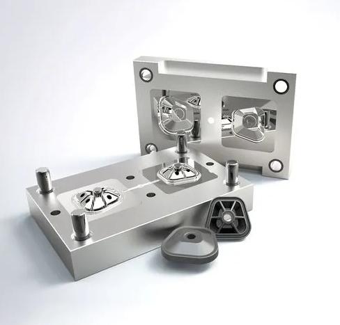
Injection molding stands as a prevalent manufacturing process renowned for its ability to fabricate intricate and precise structures by injecting molten plastic into a mold cavity. This method deposits polymer into a mold where it cools and solidifies, culminating in the production of the final item. The injection molding technique bears a significant influence on the quality of the end product.
Material Selection in Injection Molding
Selecting the appropriate material for injection molding is paramount to attaining a high-quality end result. Materials with a higher melt flow index (MFI) or viscosity often yield superior part quality, while those with a lower MFI or viscosity may lead to defects such as warping, sink marks, or flash. The MFI denotes the rate at which a material flows through the mold, thus opting for a material with a high MFI ensures thorough and consistent mold filling.
Temperature Control in Injection Molding
Temperature regulation of the molten plastic holds paramount importance in the injection molding process. Excessive temperatures can cause plastic degradation, resulting in flaws such as discoloration or bubble formation. Conversely, insufficient temperatures may lead to uneven plastic flow, resulting in incomplete mold filling or voids in the finished product. The appropriate temperature range is typically specified by the material supplier, emphasizing the necessity of injecting plastic at the prescribed temperature.
Pressure Management in Injection Molding
Injection pressure plays a pivotal role in determining the quality of the final product. High-pressure injection often yields superior component quality and surface finish, while low-pressure injection may result in incomplete mold filling, voids, or sink marks. The injection pressure is contingent upon the size, intricacy of the item, and the properties of the plastic utilized.
Cooling Dynamics in Injection Molding
The cooling rate of the plastic post-injection significantly impacts the final product’s quality. Gradual cooling may result in warping or other defects, whereas rapid cooling can enhance product quality and reduce errors. Mold design and the arrangement of cooling channels within it often dictate the cooling rate, necessitating consistent cooling throughout the part to mitigate stress-induced defects.
Mold Design Considerations
Well-designed molds facilitate even filling and prevent faults such as sink marks and warping. Mold design is influenced by factors like the component’s size, intricacy, and the plastic’s properties. It’s imperative to construct molds accounting for plastic shrinkage during cooling and solidification.
Additional Factors Affecting Product Quality
Beyond the aforementioned aspects, various other factors can impact the final product’s quality. Contaminants or impurities in the plastic, additives or fillers, injection speed, and duration are among these variables. Rigorous control of these factors is essential to ensure the production of high-quality, defect-free products.
Crafting effective explosion-proof lighting systems necessitates a meticulous approach encompassing various elements, from the classification of hazardous zones to the careful selection of fixtures and installation procedures. This article delves into the crucial design considerations for explosion-proof lighting, shedding light on the fundamental principles and methodologies that uphold safety standards in perilous environments.
Understanding Hazardous Area Classification for Designing Explosion-proof Lighting
Classifications: Hazardous areas are categorized based on the presence and concentration of flammable substances, coupled with the likelihood of ignition. The classifications typically include Class I (gas), Class II (dust), and Class III (fibers and flyings), each with subdivisions delineating the nature and extent of the hazard.
Zone Classification: Further delineating the level of risk within hazardous areas, zone classifications range from Zone 0 (high risk) to Zone 2 (low risk) for gases, and Zone 20 (high risk) to Zone 22 (low risk) for dust.
Fixture Selection and Certification in Explosion-Proof Lighting
Explosion-Proof Fixture Design: Specially engineered to prevent the ignition of flammable substances, these fixtures boast robust construction and sealed enclosures that withstand internal pressures generated by explosions without propagating ignition beyond the enclosure.
Materials and Construction: Typically crafted from durable materials like cast aluminum, stainless steel, or fiberglass-reinforced plastic, fixture materials are chosen based on environmental corrosiveness, ambient temperature, and mechanical stress factors.
Enclosure Ratings and Certifications: Lighting fixtures must meet stringent certification standards to ensure safety and regulatory compliance. Common certifications include ATEX (European Union), UL (Underwriters Laboratories), and IECEx (International Electrotechnical Commission Explosive Atmospheres), each indicating rigorous testing and adherence to safety protocols.
Choosing the Right Fixture Type: Fixture selection hinges on specific hazardous area requirements, such as the presence of gases, vapors, or dust. Enclosed fixtures, explosion-proof floodlights, LED fixtures, and emergency lighting fixtures are among the common types tailored to various needs.
Optimal Lighting Design in Explosion-Proof Lighting
Task Requirements and Illumination Levels: Tailor lighting design to meet specific tasks and required illumination levels, ensuring safe working conditions without over-illumination.
Uniformity of Illumination: Aim for consistent light distribution to minimize shadows and ensure visibility across the workspace.
Fixture Placement and Spacing: Strategically position fixtures to achieve optimal coverage while avoiding excessive overlap, optimizing energy efficiency and uniformity.
Lighting Control and Flexibility: Incorporate dimming controls and emergency lighting systems to adjust illumination levels and ensure continuous operation during power outages or emergencies.
Glare Control: Employ fixtures with appropriate shielding or diffusers to minimize glare, enhancing visual comfort and safety.
Color Rendering and Temperature: Consider the color rendering index (CRI) and temperature of fixtures to ensure accurate color perception and task performance alignment.
Maintenance and Inspection in Explosion-Proof Lighting
Scheduled Maintenance Routine: Establish routine inspection, testing, and servicing intervals based on environmental factors and regulatory requirements.
Visual and Electrical Inspection: Conduct regular visual and electrical inspections to identify damage, corrosion, or electrical faults, ensuring fixture integrity and safety.
Lamp Replacement: Replace lamps as recommended, following proper procedures to maintain safety and performance standards.
Seal Integrity and Cleaning: Check seals for integrity and cleanliness, and develop cleaning procedures to remove contaminants and maintain fixture performance.
Documentation and Record-Keeping: Maintain detailed records of maintenance activities to ensure compliance and accountability.
Conclusion
Explosion-proof lighting systems serve as vital safety mechanisms in hazardous environments, guiding personnel and illuminating workspaces while mitigating explosion risks. Effective design hinges on a comprehensive understanding of hazardous area classifications, meticulous fixture selection, optimal lighting design, and diligent maintenance practices, ensuring continued safety and compliance in high-risk settings.
The offshore oil and gas industry stands as a cornerstone of the global energy supply chain, yet it harbors inherent dangers. Oil rig accidents can unleash severe consequences, from injuries to environmental calamities and economic losses. In this piece, we delve into the various types of various types of oil rig accidents and the injuries they can inflict upon workers, shedding light on critical safety concerns in this high-stakes industry.
Types of Oil Rig Accidents
Blowouts: A blowout, the stuff of nightmares in the offshore oil industry, occurs when high-pressure oil or gas erupts uncontrollably from the well. Triggered by equipment failures, human error, or a blend of factors, blowouts often lead to catastrophic explosions. Resulting injuries can include severe burns, traumatic injuries, exposure to toxic gases, and psychological trauma.
Fires and Explosions: These incidents, stemming from equipment malfunctions, electrical faults, or human error, pose significant risks. Fires and explosions can cause extensive damage, including rig destruction, and result in severe burns, smoke inhalation, and traumatic injuries to workers.
Falls and Falling Objects: Given the towering structures of oil rigs, workers are susceptible to falls from heights or being struck by falling objects. These accidents can cause broken bones, head injuries, spinal cord damage, and lacerations, emphasizing the importance of stringent safety measures.
Weather-Related Incidents: Offshore rigs are at the mercy of adverse weather conditions, such as storms and hurricanes, which can lead to rig movements, damage, or topples. Workers may suffer traumatic injuries or drowning, emphasizing the need for proactive safety measures and emergency response plans.
Collisions and Groundings: Collisions between vessels and oil rigs or groundings of rigs can result in structural damage, oil spills, and environmental damage. Injuries may include traumatic injuries, drowning, and environmental impact, highlighting the importance of navigational vigilance and equipment maintenance.
Role of Simulation Training
Simulation technology emerges as a crucial tool in preventing oil rig accidents and injuries, offering several benefits:
Realistic Scenario Practice: Workers can simulate realistic accident scenarios, enhancing their understanding of emergency dynamics and response strategies.
Preventative Measures: Simulation training aids in hazard recognition, empowering workers to proactively identify and mitigate risks.
Response Preparedness: Emergency training simulation prepares workers for swift and effective responses in emergencies, guiding them through assessments, task prioritization, and necessary actions.
Hands-On Experience: Simulation training provides practical experience, boosting confidence and competence in operating equipment, using safety gear, and applying protocols.
Environmental Protection: Simulation training extends to minimizing environmental damage, ensuring workers can contain pollutants and protect the ecosystem in case of accidents.
Conclusion
In conclusion, while the offshore oil and gas industry is vital for global energy needs, it is not without peril. Understanding and addressing these risks demand concerted efforts from rig operators, workers, and regulatory bodies. By prioritizing safety, leveraging advanced technologies like simulation training, and fostering collaboration, the industry can mitigate risks and safeguard lives, the environment, and its own sustainability.
Tension control systems stand as linchpins in ensuring seamless material movement through labeling and packaging machinery, catering to a spectrum of industries. With the ability to maintain uniform tension, they safeguard against damage and uphold the quality of packaged goods. In this exploration, we unravel the intricacies of tension control systems, their critical importance, applications, and the transformative innovations driving the industry forward.
Deciphering Tension Control Systems
Mechanisms: Tension control systems are meticulously designed mechanisms tasked with regulating material tension during packaging. They meticulously manage speed and torque of crucial components like rollers, brakes, clutches, and motors, ensuring precise control over material handling.
Objective: The paramount objective of these systems lies in sustaining consistent tension levels throughout the packaging process, irrespective of material thickness, speed variations, or environmental factors. By upholding this uniformity, manufacturers circumvent issues like wrinkling, tearing, or label misalignment, thereby enhancing product quality and bolstering brand reputation.
Crucial Role in Labeling Machinery
1. Precision Label Placement: Tension control systems orchestrate labels’ feeding at the precise speed and tension, facilitating accurate placement on products or packaging surfaces. This precision is instrumental in maintaining brand consistency and effectively conveying essential information.
2. Prevention of Label Damage: By exerting control over tension levels, these systems avert label stretching or distortion during application, preserving their integrity. This ensures labels adhere smoothly, devoid of wrinkles or creases, thereby enhancing product aesthetics.
3. Minimization of Production Waste: Consistent tension control curtails material waste by preventing misaligned or damaged labels. This reduction in rework mitigates production costs associated with discarded materials, driving overall efficiency and profitability.
4. Optimized Production Efficiency: With precise tension control, labeling machinery operates at optimal speeds without compromising label quality. This maximizes throughput, ensures a steady production flow, and augments overall efficiency and output.
5. Compliance and Regulatory Standards: Tension control systems facilitate adherence to regulatory standards and industry requirements, ensuring labels comply with labeling laws governing product information, safety warnings, and other mandatory elements.
6. Enhanced Brand Image: Consistently well-applied labels contribute to a positive brand image and consumer perception. Tension control systems play a pivotal role in maintaining label consistency and quality, fostering brand trust and loyalty.
Applications Across Packaging Machinery
1. Web Handling: Essential for guiding flexible materials (webs) through packaging machinery, tension control systems maintain consistent tension, averting wrinkles, tears, or misalignment.
2. Bagging and Pouching: These systems regulate packaging material tension during forming, filling, and sealing processes, crucial for achieving tight seals and preventing spillage or contamination.
3. Wrapping and Sealing: Vital in wrapping machines, tension control systems ensure even application of shrink films or stretch films around products, maintaining integrity during transportation and storage.
4. Cartoning: Employed to manage carton blanks or packaging materials’ tension, these systems produce neatly folded and securely sealed cartons.
5. Case Packing and Palletizing: Tension control systems ensure packaging materials are applied with the right tension, maintaining product stability and integrity during transportation and storage.
6. Converting Processes: Utilized in various converting processes like slitting and cutting, these systems ensure precise control over material tension levels, minimizing waste and maintaining product quality.
Innovations Driving the Industry Forward
1. Advanced Sensor Technology: Incorporating real-time feedback tension sensors, modern tension control systems offer greater accuracy and sensitivity, allowing for finer adjustments and control over the packaging process.
2. Integrated Servo Drives: Revolutionizing tension control, integrated servo drives offer precise control over motor speed and torque, enabling synchronized operation and optimal tension management.
3. Intelligent Control Algorithms: Sophisticated algorithms optimize tension levels based on material properties, machine speed, and environmental conditions, minimizing errors and maximizing efficiency.
4. Web Guiding Systems: Utilizing sensors and actuators, web guiding systems detect and correct deviations in web alignment, preventing edge damage and ensuring precise tensioning.
5. Cloud-Based Connectivity and Data Analytics: Offering remote monitoring and analysis, cloud-based systems enable proactive maintenance, predictive analytics, and performance optimization.
6. User-Friendly Interfaces: Featuring intuitive controls and graphical displays, modern interfaces allow operators to monitor tension levels, adjust settings, and troubleshoot issues with ease.
In Conclusion
Tension control systems represent the backbone of the labeling and packaging industry, ensuring precision, efficiency, and reliability at every turn. As manufacturers navigate an evolving market landscape, embracing innovative tension control technologies becomes paramount. By harnessing these advancements, manufacturers can position themselves for success, delivering superior products and maintaining a competitive edge in the industry landscape.
Marine lifebuoys represent a beacon of hope amidst the unpredictability of the open sea, serving as indispensable tools for ensuring survival during emergencies. In this exploration, we uncover the significance of marine lifebuoys and their pivotal role in maritime safety.
A Brief Evolution
The concept of buoyant devices aiding water rescues traces back centuries. Initially simple rings crafted from wood, lifebuoys have evolved significantly with advancements in materials and technology. Today, they stand as highly efficient and standardized marine lifesaving devices.
Design and Composition
Buoyancy Material: Marine lifebuoys are crafted from buoyant materials like high-density polyethylene or foam-filled plastics, ensuring they remain afloat even in harsh marine conditions.
Shape and Size: Traditionally circular, lifebuoys offer stability and ease of handling. Standard sizes range between 24 to 30 inches in diameter, providing ample buoyancy for individuals in distress.
Visibility Features: Bright colors such as orange, yellow, or red coupled with reflective strips enhance visibility, crucial for quick retrieval during emergencies.
Attachment Points: Equipped with fixtures for rope attachment, lifebuoys facilitate securing to the individual in distress or other rescue equipment.
Grab Lines or Ropes: Some feature grab lines aiding both individuals in distress to hold on and rescuers to pull them to safety.
Durability and Resistance: Constructed with materials resilient to saltwater, UV radiation, and rough handling, ensuring longevity and effectiveness.
Compliance with Regulations: Governed by international maritime regulations, lifebuoys adhere to standards ensuring consistency and effectiveness across maritime operations.
Functionality
Buoyancy and Floatation: Providing immediate buoyancy, lifebuoys offer stability and support to individuals in distress.
Aid in Water Rescue: Deployed swiftly during emergencies, lifebuoys assist individuals until rescue personnel arrive, allowing them to hold on while awaiting assistance.
Marking and Signaling: Highly visible, lifebuoys act as markers during search and rescue operations, aiding in locating individuals in low-light conditions or rough seas.
Assistance in Retrieval: Featuring grab lines, lifebuoys enable rescuers to pull individuals to safety, guiding them back to the vessel or another secure location.
Emergency Preparedness: Strategically positioned for quick access, lifebuoys are integral to emergency preparedness, ensuring readiness for swift deployment.
Innovative Utilization
From recreational water safety to industrial applications, lifebuoys find versatile use:
Recreational Water Safety: Lifeguards employ lifebuoys at beaches and pools for swift water rescues.
Waterfront Safety and Rescue Operations: Positioned along waterfronts, lifebuoys aid in emergencies, ensuring rapid assistance.
Waterfront Public Safety Campaigns: Symbols of water safety, lifebuoys feature in campaigns advocating drowning prevention.
Flood and Swift Water Rescue: During floods, lifebuoys assist in rescuing individuals trapped in fast-moving water.
Ice Rescue Operations: Essential in regions with frozen bodies of water, lifebuoys aid in ice rescue operations.
Waterfront Security and Surveillance: Equipped with monitoring devices, lifebuoys enhance waterfront security.
Industrial and Commercial Applications: Integrated into safety protocols, lifebuoys offer emergency flotation assistance.
Water-based Events and Competitions: Deployed along race courses, lifebuoys ensure participant safety during events.
Personal Watercraft Safety: Enthusiasts carry compact inflatable lifebuoys for personal safety during water activities.
Training and Preparedness
Proficient utilization hinges on proper training among crew members and passengers, ensuring swift and coordinated responses during emergencies. Regular drills and exercises instill proficiency in deploying lifesaving equipment, bolstering safety measures at sea.
Conclusion
In the realm of maritime safety, the marine lifebuoy remains an emblem of preparedness and resilience. Its evolution, stringent standards, and versatile applications underscore its indispensable role in safeguarding lives amidst the vastness of the open sea.
Material Preparation: Prior to stamping, meticulous material selection and sourcing are imperative. Various metals like steel, aluminum, and copper offer unique properties influencing the final product’s characteristics. Once the suitable material is secured, it undergoes preparation in the form of coils or sheets, primed for the stamping press.
Tool and Die Setup: This pivotal step revolves around meticulous design and engineering. Skilled professionals craft dies, specialized tools essential for shaping the metal. These dies are meticulously tailored to match the desired product design, ensuring precision throughout the stamping process. Tooling preparation entails die assembly, alignment, and calibration to optimize performance.
Metal Stamping Operations: Metal stamping encompasses an array of operations shaping the material. Blanking cuts the outline of desired parts from the metal sheet, while piercing creates holes or perforations. Forming molds the metal into desired shapes, and bending achieves angled or curved features. Coining applies high pressure to create precise, intricate details, and deep drawing pulls the metal sheet into a die cavity to form complex, three-dimensional shapes.
Secondary Operations: Following primary stamping operations, secondary processes refine the parts further. Trimming removes excess material, deburring eliminates sharp edges or burrs, and hole punching or notching creates specific features required for the final product.
Inspection and Quality Control: To uphold integrity, inspection and quality control are paramount. Dimensional accuracy checks verify parts meet specified measurements, surface finish evaluation ensures desired texture, and defect detection eliminates any flawed parts, maintaining high quality standards.
Techniques Employed in Metal Stamping
Progressive Stamping: This progressive die stamping technique, ideal for high-volume production, involves consecutive stamping operations performed in a progressive die. As the metal strip progresses through the die, each station performs a specific operation, gradually forming the desired shape. It offers cost-effectiveness, reduced material waste, and increased production speed.
Transfer Stamping: Suitable for complex parts or low- to medium-volume production, transfer stamping involves transferring individual metal blanks from one station to the next for various stamping operations. It allows flexibility in handling larger or thicker materials, enabling production of intricate parts.
Deep Drawing: Employed for cylindrical or box-shaped parts with significant depth, deep drawing pulls the metal sheet into a die cavity using a punch, shaping it into the desired form. It offers excellent material utilization, enabling creation of seamless, hollow structures.
Blanking and Piercing: These techniques focus on cutting shapes and creating holes in the metal sheet, respectively. Blanking removes desired shapes, while piercing creates openings or perforations, often utilized as primary operations before further forming or assembly processes.
Coining: Precisely creating intricate details, coining involves applying high pressure to the metal between specially designed dies, shaping the material with extreme accuracy. It is commonly used for precise embossing or decorative elements on products like jewelry or high-end consumer goods.
Troubleshooting in Metal Stamping
Despite meticulous planning, challenges may arise during stamping, such as material fractures or misalignment. A systematic approach to troubleshooting is crucial, identifying root causes for effective solutions. Techniques like adjusting press settings or optimizing material properties can resolve many stamping issues, enhancing production efficiency.
In Conclusion
Mastering the metal stamping process demands a comprehensive understanding of its steps and techniques. From material preparation to tool setup and stamping operations, each stage plays a crucial role in achieving precise and high-quality parts. Techniques like progressive stamping, transfer stamping, deep drawing, blanking, piercing, and coining offer versatility and efficiency, shaping the future of product development and innovation across industries. With meticulous quality control and problem-solving approaches, manufacturers can overcome challenges and enhance their stamping operations, ensuring continued reliability and cost-effectiveness in manufacturing.
Sterilization stands as a cornerstone in healthcare, safeguarding patients and professionals by thwarting the spread of infections. Among the array of sterilization methods, autoclaving shines as a widely embraced technology, thanks to its proven efficacy in eradicating bacteria. In this discourse, we embark on a journey through the realm of autoclave sterilization, deciphering its process intricacies, extolling its virtues, and unraveling the pivotal considerations for optimal outcomes.
Decoding the Autoclave Sterilization Process
Autoclave sterilization entails subjecting instruments, equipment, and supplies to high-pressure steam at temperatures surpassing the boiling point. This formidable mix of heat and moisture creates an environment hostile to microorganisms, effectively neutralizing bacteria, viruses, fungi, and spores. This method finds its niche in sterilizing heat-resistant medical apparatus like surgical tools, dental gear, and laboratory glassware.
The sterilization cycle typically commences with pre-vacuuming, eliminating air to enhance steam penetration. Subsequently, the autoclave elevates the temperature to the requisite range, typically between 121 and 134 degrees Celsius (250 and 273 degrees Fahrenheit), while maintaining pressure between 15 and 30 pounds per square inch (psi). The duration of exposure varies based on instrument type, load size, and sterilization goals. Upon cycle completion, the autoclave gradually depressurizes, allowing instruments to cool before safe retrieval.
Embracing the Advantages of Autoclave Sterilization
Autoclave sterilization emerges as a champion in destroying an array of microorganisms, including notoriously resilient bacterial spores. By harnessing the trifecta of heat, pressure, and steam, even the hardiest pathogens meet their demise, mitigating the risk of healthcare-associated infections.
For healthcare facilities, autoclaving presents a cost-effective alternative. Once the initial investment in autoclave equipment is made, operational expenses remain modest compared to other sterilization methods, such as chemical sterilization. Autoclaves boast a generous instrument load capacity, facilitating efficient processing of multiple items simultaneously, thereby saving time and resources.
Moreover, autoclave sterilization champions environmental sustainability. Eschewing harsh chemicals and toxic byproducts, this method aligns with sustainable practices. The use of steam and heat obviates the need for packaging, curbing waste generation in healthcare establishments.
Navigating Critical Considerations for Optimal Autoclave Sterilization
To realize optimal autoclave sterilization outcomes, adherence to specific rules and best practices is paramount.
Proper Instrument Preparation: Thorough cleaning and decontamination of instruments precede autoclaving. Removal of organic debris is imperative for effective steam penetration. Instruments should be disassembled as per manufacturer guidelines.
Load Configuration: Prudent placement of instruments within the autoclave chamber is essential. Overcrowding stifles steam circulation, imperiling sterilization. Ample spacing ensures steam access to all surfaces, particularly crucial for devices with lumens or intricate forms.
Packaging Considerations: Some instruments may necessitate post-autoclaving packaging to preserve sterility. Selection of sterilization pouches or wraps should consider compatibility with autoclave processes and instrument types. Proper sealing guards against recontamination during storage and transit.
Cycle Selection and Validation: Autoclaves offer diverse sterilization cycles tailored to instrument types, load sizes, and sterilization levels. Validation of chosen cycles ensures compliance with sterilization parameters and regulatory standards.
Monitoring and Documentation: Regular monitoring of autoclave performance is imperative for consistent sterilization outcomes. Biological indicators gauge sterilization process efficiency, while physical indicators verify time, temperature, and pressure. Comprehensive documentation ensures traceability and quality assurance.
In Conclusion
Autoclave sterilization stands as the bedrock of a safe, infection-free healthcare milieu. Its efficacy, cost-effectiveness, and environmental friendliness render it indispensable in healthcare facilities. By adhering to meticulous protocols, healthcare establishments uphold the highest standards of infection control and patient safety, ensuring the reliability and efficacy of autoclave sterilization processes.
Oil rigs, also known as drilling platforms or offshore platforms, stand as testament to human engineering prowess, facilitating the extraction of valuable hydrocarbon resources from beneath the ocean floor. These structures are pivotal to the global oil and gas industry, enabling the extraction of crude oil and natural gas from offshore reserves. In this comprehensive guide, we explore the diverse types of oil rigs tailored to unique offshore environments and drilling demands, alongside considerations for selecting the optimal rig for your project.
Exploring the Spectrum of Oil Rigs:
Fixed Platform Rigs:
Fixed platform rigs are stalwart fixtures, firmly anchored to the ocean floor. They come in various configurations, including:
Jack-up Platforms: Deployed in shallow waters, supported by adjustable legs.
Conductor Support Platforms: Designed for deep-water drilling, supported by vertical conductors.
Caisson Platforms: Massive hollow structures, utilized in shallow to ultra-deep waters.
Semi-Submersible Rigs:
Semi-submersible rigs offer versatility, partially submerged and regulated by ballast systems. Renowned for their stability, they operate effectively in various water depths and adverse weather conditions.
Drillship Rigs:
Drillship rigs, resembling mobile vessels, boast agility and mobility for deepwater and ultra-deepwater drilling. Ideal for exploratory drilling in remote offshore locations.
Tension Leg Platform (TLP) Rigs:
TLP rigs excel in deepwater drilling projects, anchored to the seabed with tension-maintaining tethers or tendons, ensuring stability amid significant wave motion.
Floating Production Storage and Offloading (FPSO) Rigs:
FPSO rigs serve a dual purpose, not only drilling but also processing and storing crude oil. Positioned above offshore fields, they oversee oil processing until tanker ships transport it ashore.
Compliant Tower Rigs:
Compliant tower rigs, tailored for water depths of 300 to 2,000 feet, feature slender towers anchored to the seabed. Their design enables them to sway with natural waves, ensuring operational stability.
Subsea Rigs:
A cutting-edge innovation, subsea rigs eliminate the need for conventional above-water platforms, conducting drilling operations directly from the seabed. Ideal for ultra-deepwater drilling, they offer remote operability from surface vessels.
Articulated Column Rigs:
Articulated column rigs are specialized for Arctic conditions, anchored by a single vertical column that pivots to maintain stability amidst ice movements and severe weather.
Mini Rigs:
Mini rigs, compact and portable, cater to shallow water or near-shore drilling projects. Easily transported by truck, they offer swift deployment for minor drilling endeavors.
Selecting the Right Oil Rig: Considerations and Guidelines:
Drilling Location:
Pinpoint the drilling site’s specifics, considering geographical factors, proximity to shore, and water depth.
Water Depth Assessment:
Different rigs are suited to varying water depths. Match the rig type to the depth range of the drilling location.
Drilling Objectives Clarification:
Define the purpose of drilling—exploration, production, or maintenance—to align rig selection with project goals.
Environmental Conditions Evaluation:
Assess environmental factors like weather patterns and currents to choose a rig capable of withstanding local conditions.
Mobilization and Demobilization:
Consider ease of rig transportation and deployment, balancing mobility with operational requirements.
Budgetary and Cost Constraints:
Evaluate project budget and operational costs to select a rig that aligns with financial parameters.
Regulatory Compliance and Permitting:
Ensure adherence to regulatory standards and obtain necessary permits for drilling activities.
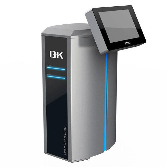
Safety and Risk Assessment:
Prioritize rig safety features and emergency response capabilities, conducting thorough risk evaluations. The drilling simulation training system can be of great assistance in assessing safety and risk in oil rigs. It is specifically designed for training individuals on all aspects of safe and effective drilling rig operations, using a display screen, the 3D animation depicting the working conditions, while sound effects imitating a real rig floor create a fully engaging and immersive training environment.
Consultation and Expert Advice:
Seek guidance from drilling professionals and industry experts to inform rig selection decisions.
Flexibility and Adaptability:
Opt for rigs that offer flexibility to operate in diverse conditions and adapt to changing project requirements.
Maintenance and Availability Considerations:
Assess rig availability and maintenance schedules to ensure timely project execution.
Environmental Impact Mitigation:
Choose environmentally conscious rig options to minimize ecological harm from drilling activities.
Conclusion:
Oil rigs represent the pinnacle of human innovation and engineering prowess, facilitating the extraction of invaluable energy resources from beneath the ocean’s depths. Selecting the right rig entails a meticulous evaluation of project requirements, environmental factors, regulatory compliance, and budgetary considerations. By aligning rig selection with project objectives and operational realities, stakeholders can navigate the complexities of offshore drilling with confidence and efficiency, ensuring the sustainable extraction of Earth’s precious energy reserves.
In the dynamic landscape of the printing industry, maintaining impeccable product quality is non-negotiable. Every flaw, no matter how small, can reverberate into significant consequences. This is where printing inspection steps in as the sentinel of quality, enabling businesses to identify and rectify errors before they reach consumers’ hands. From packaging materials to labels and printed electronics, the meticulousness of inspection processes is paramount. In this comprehensive discourse, we navigate through the importance of printing inspection, its methodologies, challenges, innovative technologies, and its pivotal role in upholding quality assurance standards across various industries.
Significance of Printing Inspection Across Different Sectors:
Printing inspection holds undeniable significance across diverse industries where printed materials serve indispensable functions. Whether it’s packaging for consumer goods, labels for pharmaceutical products, or informational brochures, the quality and precision of printed materials directly influence brand reputation, consumer safety, and adherence to regulatory standards.
Ensuring Quality and Consistency:
Industries like consumer packaged goods (CPG), cosmetics, and food and beverage rely on packaging for brand identity and product presentation. Printing inspection ensures that packaging materials meet stringent quality standards, including color accuracy, print clarity, and overall aesthetics, fostering consumer trust and confidence.
Compliance with Regulatory Standards:
In regulated sectors such as pharmaceuticals and food packaging, printing inspection is imperative for compliance with strict regulatory requirements. Printed materials often convey critical information like dosage instructions and safety warnings. Any inaccuracies or defects in printing could lead to severe consequences, including regulatory penalties and compromised consumer safety.
Brand Protection and Reputation Management:
Across all industries, safeguarding brand integrity is paramount. Printing inspection plays a pivotal role in upholding brand reputation by ensuring that printed materials adhere to brand guidelines and quality standards. Consistent high-quality printing reflects positively on the brand, reinforcing its image as trustworthy and reliable.
Waste Reduction and Cost Savings:
Printing defects can result in substantial material wastage and production inefficiencies. Inspection systems help minimize waste, reduce rework, and optimize resource utilization by detecting errors early in the printing process, leading to significant cost savings for manufacturers and bolstering operational efficiency.
Enhancing Consumer Experience:
Printed materials serve as a conduit of communication between businesses and consumers. Clear, accurate printing enhances the consumer experience by ensuring that information is legible, coherent, and error-free, thereby fostering better understanding and usability of the product.
Supporting Sustainable Practices:
Printing inspection contributes to environmentally responsible practices by minimizing printing defects and waste. By ensuring compliance with labeling regulations, inspection systems promote transparency and accountability in product information, catering to the preferences of environmentally conscious consumers.
Commonly Used Methods in Printing Inspection:
Printing inspection employs a repertoire of methods and technologies to uphold the quality and accuracy of printed materials.
Visual Inspection:
Manual Visual Inspection: Trained personnel visually scrutinize printed materials to identify defects such as misprints, smudges, and color inconsistencies.
Automated Inspection Systems: Machine vision printing inspection systems utilize high-speed cameras, image processing algorithms, and pattern recognition techniques to detect defects with precision and efficiency.
Digital Printing Inspection:
Real-Time Inspection: Inline inspection systems integrated into digital printing presses enable immediate feedback and adjustment during the printing process.
Post-Printing Inspection: Offline inspection systems analyze printed output after the printing process for defects or inconsistencies, facilitating batch-level quality control.
Statistical Process Control (SPC):
Data Analysis: Statistical methods are employed to analyze printing process data and identify trends, variations, or abnormalities.
Control Charts: Monitoring key process parameters over time and setting control limits ensures that printing processes remain within acceptable bounds.
Challenges and Considerations in Printing Inspection:
Addressing challenges in printing inspection requires a multifaceted approach encompassing technological innovation, operational optimization, and organizational readiness.
Complexity of Print Processes:
Variability in Printing Technologies: Different printing technologies pose unique challenges for inspection systems, necessitating adaptable solutions tailored to specific processes.
Diverse Substrates and Materials: Printing on various substrates requires inspection systems to accommodate diverse surface properties and printing challenges.
Defect Detection and Classification:
Detection of Subtle Defects: Some printing defects are elusive and require advanced inspection technologies with high sensitivity and specificity.
Defect Classification and Prioritization: Accurately categorizing and prioritizing defects based on severity is crucial for effective corrective action.
Speed and Throughput:
High-Speed Production Environments: Inspection systems must operate at high throughput rates to keep pace with production without causing bottlenecks.
Real-Time Inspection Requirements: Real-time inspection is essential for inline printing processes to detect defects promptly and enable immediate corrective action.
Integration with Production Workflow:
Compatibility with Equipment and Software: Seamless integration of inspection systems into existing workflows requires coordination and collaboration across different stakeholders.
Training and Expertise:
Operator Training: Adequate training ensures that operators can effectively utilize and interpret inspection systems to maximize their utility.
Technical Expertise: Maintenance and troubleshooting of inspection systems demand technical proficiency across various domains.
Cost and ROI:
Initial Investment: Implementing inspection systems entails significant upfront costs, including equipment acquisition and integration expenses.
Return on Investment (ROI): Demonstrating the ROI of inspection systems necessitates quantifying the value of improved product quality and operational efficiency over time.
Innovative Technologies to Address Challenges:
Advanced Machine Vision Systems:
Deep Learning and AI: Leveraging deep learning algorithms enhances defect detection capabilities, enabling the identification of subtle anomalies with exceptional accuracy.
Convolutional Neural Networks (CNNs): CNNs automatically learn features from printed images, facilitating defect classification and analysis.
Real-Time Monitoring and Control:
IoT-enabled Sensors: Embedded sensors monitor key process parameters in real-time, optimizing printing conditions and preempting defects.
Closed-Loop Control Systems: Feedback from sensors triggers dynamic adjustments to printing parameters, ensuring optimal print quality.
Multi-Sensor Fusion:
Integration of Multiple Inspection Techniques: Combining diverse inspection methods provides comprehensive defect detection and characterization.
Data Fusion Algorithms: Advanced algorithms analyze and correlate data from multiple sensors, enhancing the accuracy and reliability of defect detection.
Augmented Reality (AR) and Virtual Reality (VR):
AR-assisted Inspection: Overlaying digital information onto real-world views assists operators in visual inspection tasks, enhancing accuracy and efficiency.
VR-based Training Simulations: VR simulations provide immersive training experiences, enabling operators to hone their inspection skills in virtual environments.
Blockchain for Traceability and Authentication:
Blockchain Technology: Blockchain-based solutions ensure the integrity and authenticity of printing processes, fostering transparency and accountability throughout the supply chain.
Conclusion:
In the dynamic landscape of the printing industry, inspection serves as the bedrock of quality assurance, regulatory compliance, and brand integrity. By leveraging innovative technologies, addressing operational challenges, and fostering a culture of continuous improvement, businesses can navigate the complexities of printing inspection with confidence. As the industry evolves, embracing cutting-edge solutions and best practices will be instrumental in driving sustained growth and competitiveness in the global market.