The in-line width measurement system represents a significant advancement in manufacturing technology, offering real-time precision measurement capabilities that enhance product quality, increase efficiency, and reduce waste. This system is particularly crucial in industries where the accurate width of materials is critical to the performance and functionality of the final product.

Understanding the In-line Width Measurement System
The in-line width measurement system is a sophisticated technological solution designed to accurately measure the width of materials as they move along the production line. Unlike traditional measurement methods that rely on manual inspection or periodic sampling, the in-line system provides real-time data, allowing for immediate adjustments and corrections to ensure consistent product quality.
At its core, the in-line width measurement system typically consists of precision sensors, cameras, lasers, or other measurement devices strategically positioned along the production line. These sensors continuously monitor the width of the material as it passes through, capturing data with exceptional accuracy and reliability.
Key Components and Functionality of the In-line Width Measurement System
Precision Sensors
Role: Precision sensors are at the forefront of the in-line width measurement system, responsible for capturing detailed measurements of the material’s width in real-time.
Functionality: These sensors employ various technologies such as lasers, cameras, ultrasonic waves, or optical sensors to accurately measure the width of the material passing through the production line.
Placement: Sensors are strategically positioned along the production line to cover the entire width of the material, ensuring comprehensive and precise measurement coverage.
Data Processing Unit
Role: The data processing unit acts as the brain of the system, processing the measurement data collected by the sensors and performing complex calculations to determine the material width accurately.
Functionality: Using advanced algorithms, the data processing unit analyzes the raw measurement data, filters out noise, compensates for environmental factors, and calculates the precise width of the material.
Real-time Processing: The unit operates in real-time, enabling instantaneous adjustments to the production process based on the width measurement data.
Control System
Role: The control system receives the processed width measurement data from the data processing unit and implements necessary adjustments to maintain the material within the specified width tolerances.
Functionality: Depending on the production line setup and requirements, the control system can control various parameters such as conveyor speed, machine settings, tension levels, or other relevant factors to ensure consistent material width.
Closed-loop Control: The control system operates in a closed-loop manner, continuously receiving feedback from the sensors and making rapid adjustments to maintain optimal production conditions.
Feedback Mechanism
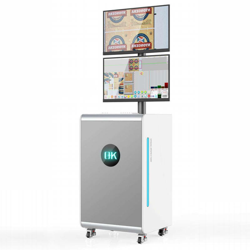
Role: The feedback mechanism provides essential information to operators and supervisors, allowing them to monitor production performance and intervene if deviations from the specified width tolerances occur.
Functionality: Real-time feedback alerts operators to any width-related issues, enabling prompt corrective actions to prevent quality defects or production disruptions.
Visualization Tools: Feedback mechanisms often include visualization tools such as graphical displays or data logging systems, allowing operators to track width measurements over time and identify trends or anomalies.
Integration Interfaces
Role: Integration interfaces facilitate seamless communication and integration of the in-line width measurement system with other components of the production line, such as PLCs (Programmable Logic Controllers), SCADA (Supervisory Control and Data Acquisition) systems, or MES (Manufacturing Execution Systems).
Functionality: Integration interfaces ensure interoperability between the width measurement system and existing production line infrastructure, enabling centralized control, data sharing, and synchronization of operations.
Compatibility: These interfaces may support industry-standard communication protocols such as OPC (OLE for Process Control) or Modbus, ensuring compatibility with a wide range of industrial automation systems.
Benefits of the In-line Width Measurement System
Enhanced Product Quality: By providing real-time measurements of material width, the system ensures consistent product dimensions within tight tolerances, resulting in higher-quality products that meet or exceed customer expectations.
Improved Efficiency: Real-time monitoring and adjustments optimize production processes, reducing material waste and minimizing downtime associated with manual inspections or adjustments. Increased efficiency leads to higher throughput and lower production costs.
Cost Savings: The system helps minimize scrap, rework, and material usage by detecting deviations from specified width tolerances early in the production process. This translates into significant cost savings over time, improving the overall profitability of manufacturing operations.
Reduced Rework and Waste: By detecting width variations in real-time, the system enables immediate corrective actions to be taken, reducing the need for rework and minimizing material waste. This contributes to a more sustainable manufacturing environment.
Increased Flexibility and Adaptability: The system can be easily integrated into existing production lines and configured to accommodate different materials, widths, and production requirements. This flexibility enables manufacturers to adapt quickly to changing market demands and production conditions.
Enhanced Process Control: Continuous monitoring of material width allows for precise control of production parameters such as machine settings, conveyor speeds, and tension levels. This results in tighter process control and greater consistency in product quality.
Compliance and Traceability: The system provides comprehensive documentation of width measurements, enabling manufacturers to demonstrate compliance with regulatory standards and quality requirements. This enhances traceability and facilitates quality assurance processes.
Applications of the In-line Width Measurement System
Textiles and Fabrics: In textile manufacturing, maintaining consistent fabric width is essential for ensuring uniformity in finished products such as clothing, upholstery, and linens. The in-line measurement system ensures that fabric rolls maintain the desired width throughout the production process, minimizing variations and defects.
Paper and Packaging: In paper mills and packaging facilities, accurate width measurement is crucial for producing rolls of paper, cardboard, and packaging materials that meet customer specifications. The system helps control the width of these materials, ensuring they are within tolerance limits and suitable for further processing or packaging.
Plastics and Films: In the plastics industry, maintaining precise width dimensions is vital for producing films, sheets, and extruded products used in packaging, construction, and other applications. The in-line width measurement system ensures that plastic materials are extruded or processed to the correct width, preventing defects and optimizing material usage.
Metal Processing: In metal processing facilities, maintaining consistent width dimensions is essential for producing metal strips, sheets, and coils used in various industries such as automotive, construction, and manufacturing. The system helps monitor and control the width of metal materials during rolling, cutting, or stamping processes, ensuring they meet tight tolerances.
Converting and Printing: In converting and printing operations, precise width measurement is crucial for ensuring accurate registration and alignment of printed materials, labels, and packaging. The in-line width measurement system helps maintain the correct width of substrates and printed materials, minimizing waste and improving print quality.
Flexible Electronics: In the production of flexible electronics such as displays, sensors, and printed circuits, maintaining uniform material width is essential for ensuring device performance and reliability. The system enables manufacturers to monitor and control the width of flexible substrates and conductive materials during the manufacturing process, optimizing yield and quality.
Medical Devices and Pharmaceuticals: In the medical device and pharmaceutical industries, precise width measurement is critical for producing components such as films, tapes, and packaging materials used in medical devices and drug delivery systems. The in-line width measurement system ensures that these materials meet stringent quality standards and regulatory requirements, ensuring patient safety and product integrity.
Food and Beverage Packaging: In food and beverage packaging facilities, accurate width measurement is essential for producing packaging materials such as films, pouches, and labels that protect and preserve food products. The system helps maintain the correct width of packaging materials, ensuring they meet hygiene standards and regulatory requirements while minimizing packaging waste.
Conclusion
In an era where precision and efficiency are paramount, the in-line width measurement system stands out as a game-changer in manufacturing. By providing real-time measurement data and enabling immediate adjustments, this innovative technology helps industries maintain the highest standards of quality while optimizing production processes.