Web inspection systems play a critical role in monitoring continuous materials like paper, plastic, textiles, and metals for defects and irregularities, ensuring high product quality. The integration of remote monitoring and diagnostics into these systems further enhances their capabilities, offering real-time oversight, improving maintenance procedures, and minimizing downtime. This article delves into the importance, benefits, and implementation strategies for remote monitoring and diagnostics in web inspection systems.
Implementation of Remote Monitoring and Diagnostics in Web Inspection Systems
Sensors and Cameras: High-resolution cameras and a variety of sensors (e.g., thickness, temperature, tension) should be installed along the web inspection line to capture detailed data.
Edge Devices: Utilize edge computing devices to preprocess data locally before transmitting it to the cloud or remote servers.
Connectivity: Ensure reliable connectivity via wired or wireless networks (e.g., Ethernet, Wi-Fi, 4G/5G).
Software Components
Data Acquisition System (DAS): Implement a DAS to collect and process data from sensors and cameras in real-time.
Remote Monitoring Software: Develop or integrate software platforms that enable remote access to inspection data, visual feeds, and system status.
Cloud Storage and Computing: Leverage cloud services for data storage, processing, and analytics.
Data Transmission and Storage
Secure Data Transmission
Encryption: Apply encryption protocols (e.g., SSL/TLS) to secure data during transmission.
Cloud Storage: Store inspection data in the cloud for scalability and ease of access.
Redundancy: Implement data redundancy strategies to prevent data loss.
Real-Time Monitoring
Dashboard Development
Custom Dashboards: Create customizable dashboards that display key performance indicators (KPIs), real-time data, and alerts.
Visualization Tools: Employ graphical tools to visualize data trends, anomalies, and inspection results.
Alerts and Notifications
Automated Alerts: Configure automated alerts for deviations, anomalies, and faults.
Notification Channels: Use multiple notification channels (e.g., email, SMS, mobile apps) to ensure timely alerts.
Diagnostics and Analysis
Machine Learning and AI
Predictive Analytics: Implement machine learning algorithms to predict potential faults based on historical and real-time data.
Anomaly Detection: Utilize AI techniques to detect anomalies that signal potential issues.
Diagnostic Tools
Root Cause Analysis: Develop tools for root cause analysis to identify and address the underlying causes of faults.
Decision Support Systems: Utilize decision support systems to provide actionable insights and recommendations.
Remote Control and Intervention
Remote Control Capabilities
Remote Adjustments: Enable remote adjustments of inspection system parameters (e.g., camera focus, sensor calibration) to optimize performance.
Automated Corrections: Implement automated correction mechanisms that can be triggered remotely based on diagnostic results.
Security Measures
Access Control: Introduce robust access control mechanisms to restrict remote access to authorized personnel only.
Audit Trails: Maintain audit trails of remote access and interventions for accountability.
Integration with Enterprise Systems
ERP and MES Integration
Data Integration: Integrate inspection data with Enterprise Resource Planning (ERP) and Manufacturing Execution Systems (MES) for comprehensive workflow management.
Remote Training: Develop remote training programs for operators and technicians to familiarize them with the remote monitoring and diagnostics system.
User Manuals and Documentation: Provide detailed user manuals and documentation for troubleshooting and system operation.
Technical Support
24/7 Support: Offer round-the-clock technical support to address any issues that may arise with the remote monitoring system.
Remote Assistance: Utilize remote assistance tools to provide real-time support and troubleshooting.
Conclusion
Remote monitoring and diagnostics for web inspection systems represent a significant advancement in manufacturing technology. By leveraging real-time data collection, advanced analytics, and predictive maintenance, companies can enhance product quality, increase operational efficiency, and achieve substantial cost savings. As industries continue to evolve, the integration of remote monitoring and diagnostics will undoubtedly become a standard practice, driving innovation and competitiveness in the manufacturing sector.
Knurled screws are distinguished by their versatility and functionality, finding applications across a broad spectrum of industries. These unique screws are engineered not only to securely fasten components but also to provide enhanced grip and ease of handling. This article delves into the intricacies of knurled screws, exploring their types, materials, applications, and how to select the right one for your specific needs.
Functions of Knurled Screws
Knurled screws are characterized by their knurled or textured surface on the head, which features a series of small ridges or grooves. This knurling enhances the grip for fingers, making it easier to tighten or loosen the screw without additional tools. Beyond functionality, the knurling also adds to the aesthetic appeal of these screws, making them suitable for applications where both practicality and design are important.
Types of Knurled Screws
Knurled screws come in various types, each designed for specific applications:
Thumb Screws: Featuring an enlarged, knurled head, thumb screws allow users to tighten or loosen the screw using their fingers, eliminating the need for tools. They are commonly used in applications requiring frequent adjustments, such as electronic equipment and machinery.
Knurled Shoulder Screws: These screws have a knurled shoulder between the head and the threaded portion. The shoulder acts as a precise stopping point when the screw is inserted into a hole, ensuring consistent positioning.
Knurled Captive Panel Screws: Designed with a captive panel feature, these screws remain attached to the panel even when loosened, preventing loss and simplifying maintenance and assembly processes.
Knurled Weld Screws: These screws have a knurled shank designed for welding onto metal surfaces, providing a secure attachment point.
Knurled Knob Screws: These screws combine the functionality of a knob with a screw. The knurled knob offers a comfortable grip, while the screw portion secures the object in place.
Knurled Chicago Screws: Made from brass, these knurled chicago screws offer excellent wear resistance and high strength. They feature a standard slot for easy installation with a slotted screwdriver.
Materials Used in Knurled Screws
Knurled screws are made from various materials to suit different environments and applications:
Stainless Steel: Known for its corrosion resistance and durability, stainless steel knurled screws are ideal for applications exposed to moisture, chemicals, and varying temperatures.
Brass: Brass knurled screws offer excellent conductivity and are often used in electronics and decorative applications due to their appealing golden appearance.
Aluminum: Lightweight and corrosion-resistant, aluminum knurled screws are commonly used in applications that require reduced weight without compromising strength.
Plastic: Plastic knurled screws provide electrical insulation and chemical resistance, making them suitable for non-metallic environments, especially in electronics and healthcare industries.
Applications of Knurled Screws
The versatility of knurled screws makes them suitable for a wide range of applications:
Electronics: Widely used in electronic equipment assembly, knurled screws offer quick, tool-free access to internal components due to their enhanced grip.
Machinery: In the machinery industry, knurled screws are used to secure parts that require frequent adjustments, such as guides and clamps.
Furniture: Knurled screws are employed in furniture assembly, enabling easy installation and maintenance for pieces that may need periodic adjustments.
Automotive: Used in various automotive components, from interior panels to engine parts, knurled screws provide a secure grip and reliable performance.
Medical Equipment: In medical settings, knurled screws are used to assemble devices and equipment where hygiene, grip, and precision are crucial.
Choosing the Right Knurled Screws
Selecting the appropriate knurled screw for your application requires consideration of several factors:
Material: Choose a material suited to the environmental conditions the screw will face. Stainless steel is ideal for harsh conditions, while plastic is better for non-metallic environments.
Thread Type: Determine the appropriate thread type (e.g., machine, wood, self-tapping) based on the materials being joined and the required load-bearing capacity.
Size and Length: Ensure the screw’s size and length are compatible with the components being fastened. A screw that’s too short might not secure the hold, while one that’s too long could cause damage.
Head Type: Different applications may require specific head types, such as flat, round, or hexagonal heads. Consider the aesthetics and functionality required.
Knurling Intensity: The intensity of the knurled pattern affects the grip. Light knurling offers a more subtle grip, while heavy knurling provides a stronger grip.
Summary
Knurled screws are a unique subset of fasteners that blend functionality and aesthetics. Their knurled design enhances grip and ease of handling, making them a preferred choice across industries such as electronics, machinery, automotive, and furniture. With various types, materials, and sizes available, selecting the right knurled screw involves careful consideration of factors like material, thread type, size, head type, and knurling intensity. By making an informed choice, you can ensure that your fastening solution meets both practical and design requirements.
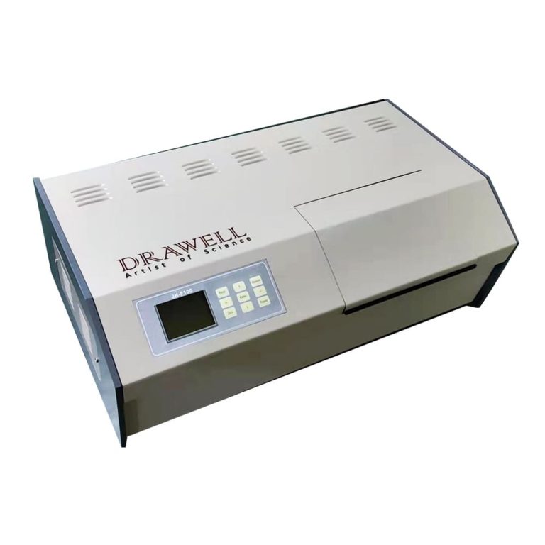
Polarimetry, a technique that measures the rotation of polarized light, plays a crucial role across various industries, including chemistry, pharmaceuticals, and food and beverage. Polarimeters are essential for determining the concentration, purity, and specific rotation of optically active substances. This article explores the practical applications of polarimeters and their significance in ensuring precision and accuracy across different fields.
Understanding the Basics of a Polarimeter
A polarimeter is an instrument that measures the rotation of plane-polarized light as it passes through an optically active substance, which can be in liquid, solid, or solution form. The degree of rotation depends on the concentration of the optically active compound and the length of the sample tube. The specific rotation, a critical parameter obtained through polarimetry, acts as a unique identifier for substances and is vital in numerous analytical processes.
Key Components of a Polarimeter
Polarizer: The polarizer generates plane-polarized light by allowing only light waves oscillating in a specific plane to pass through, creating a uniformly polarized beam.
Sample Tube or Cell: This clear container holds the substance being analyzed. The tube’s length and the substance’s concentration influence the degree of light rotation.
Analyzer: Positioned after the sample tube, the analyzer is another polarizing element that can be rotated to detect changes in the light’s orientation caused by the optically active substance.
Light Source: A stable light source, typically a sodium lamp, produces the light beam that passes through the polarizer, sample, and analyzer. The wavelength is usually standardized for consistent measurements.
Readout Scale: The polarimeter includes a readout scale or digital display to indicate the angle of the analyzer’s rotation, which is then used to calculate the specific rotation of the sample.
Wide Practical Applications of a Polarimeter
Applications in Chemistry
Chiral Molecule Analysis: Polarimeters are crucial for studying chiral molecules with optical activity, particularly in the pharmaceutical industry, where the purity and concentration of chiral compounds affect drug efficacy.
Quality Control in Chemical Manufacturing: Polarimeters provide real-time data on chemical solution composition, ensuring that products meet strict quality standards.
Applications in Pharmaceuticals
Drug Development and Formulation: Polarimetry assists in accurately formulating drugs with specific concentrations of active ingredients, vital for the efficacy and safety of pharmaceutical products.
Quality Assurance in Pharmaceutical Production: Polarimeters verify the purity of raw materials and monitor the consistency of final products during the quality assurance process.
Applications in the Food and Beverage Industry
Sugar Content Determination: Polarimeters are widely used to measure sugar content, especially in the production of beverages, jams, and confectionery, ensuring consistent sweetness and product quality.
Quality Control in the Brewing Industry: Polarimetry monitors sugar concentration during fermentation, ensuring the production of high-quality beverages.
Applications in Instrumentation and Technology
Automatic and Digital Polarimeters: Modern automatic polarimeters feature automation and digital enhancements for more efficient and accurate measurements, improving usability and reliability.
Temperature Control Systems: Many polarimeters include temperature control systems, crucial for accurate and reproducible measurements across varying temperatures.
Educational and Research Use
Polarimeters are invaluable in educational settings and research laboratories, where they help students and researchers understand optical activity and conduct experiments that drive scientific advancements.
Conclusion
Polarimeters are indispensable tools in ensuring accuracy, quality, and efficiency across various industries. From pharmaceutical research to food and beverage quality control, these instruments continue to be essential for professionals and researchers dedicated to precision and reliability.
Oil and gas exploration and production are vital components of the global energy landscape, supplying the energy needed for industrial, commercial, and residential activities. This complex process involves searching for hydrocarbon reservoirs beneath the Earth’s surface, extracting them, and processing them into essential energy resources.
Understanding the Processes of Oil and Gas Exploration and Production
The Exploration Process
Seismic Surveys
Seismic surveys are a crucial step in oil and gas exploration. By utilizing advanced technologies such as 3D and 4D seismic imaging, geophysicists can create detailed subsurface maps. These surveys generate shockwaves through controlled explosions or vibrations, with the reflections helping to identify potential hydrocarbon reservoirs.
Geological and Geophysical Studies
Understanding the geological and geophysical characteristics of a region is vital for identifying areas with potential hydrocarbon deposits. Geologists analyze surface rock formations, while geophysicists study subsurface structures using a variety of techniques to pinpoint likely reservoir locations.
Exploratory Drilling
Once a promising area is identified, exploratory drilling is initiated. This process involves drilling exploratory wells to confirm the presence of oil or gas. Advanced drilling technologies like directional and horizontal drilling enhance the accuracy and efficiency of this phase.
The Production Process
Reservoir Characterization
Before production can begin, it’s essential to characterize the reservoir to determine its size, permeability, and other critical properties. This information is vital for developing an effective production strategy.
Drilling and Well Construction
To extract oil or gas, wells are drilled into the reservoir using drilling rigs and specialized equipment. Well construction involves installing casing and cementing to ensure stability and prevent environmental impact.
Enhanced Oil Recovery (EOR)
As reservoirs mature, traditional extraction methods may become less effective. EOR techniques, such as injecting steam, chemicals, or gases into the reservoir, are employed to increase recovery rates and extend the reservoir’s life.
Surface Facilities and Processing
Extracted oil and gas contain impurities that must be removed before reaching consumers. Surface facilities, including separation units and processing plants, play a crucial role in purifying the hydrocarbons and separating oil, gas, and water.
Transportation and Distribution
After processing, the extracted oil and gas are transported to refineries and end-users. Pipelines, tankers, and, in some cases, liquefied natural gas (LNG) facilities are used to transport these valuable resources.
Challenges and Innovations in Oil and Gas Exploration and Production
Environmental Concerns
The oil and gas industry faces scrutiny due to environmental concerns. Innovations such as environmentally friendly drilling fluids, low-emission technologies, and sustainable practices are being developed to reduce the industry’s environmental impact.
Digitalization and Automation
The integration of digital technologies, automation, and artificial intelligence is transforming the E&P sector. These innovations, ranging from smart drilling systems to data analytics for predictive maintenance, improve efficiency and reduce operational risks.
Renewable Energy Integration
With an increasing emphasis on renewable energy, oil and gas companies are exploring sustainable practices and investing in alternative energy solutions. Some companies are diversifying their portfolios by investing in renewable energy projects.
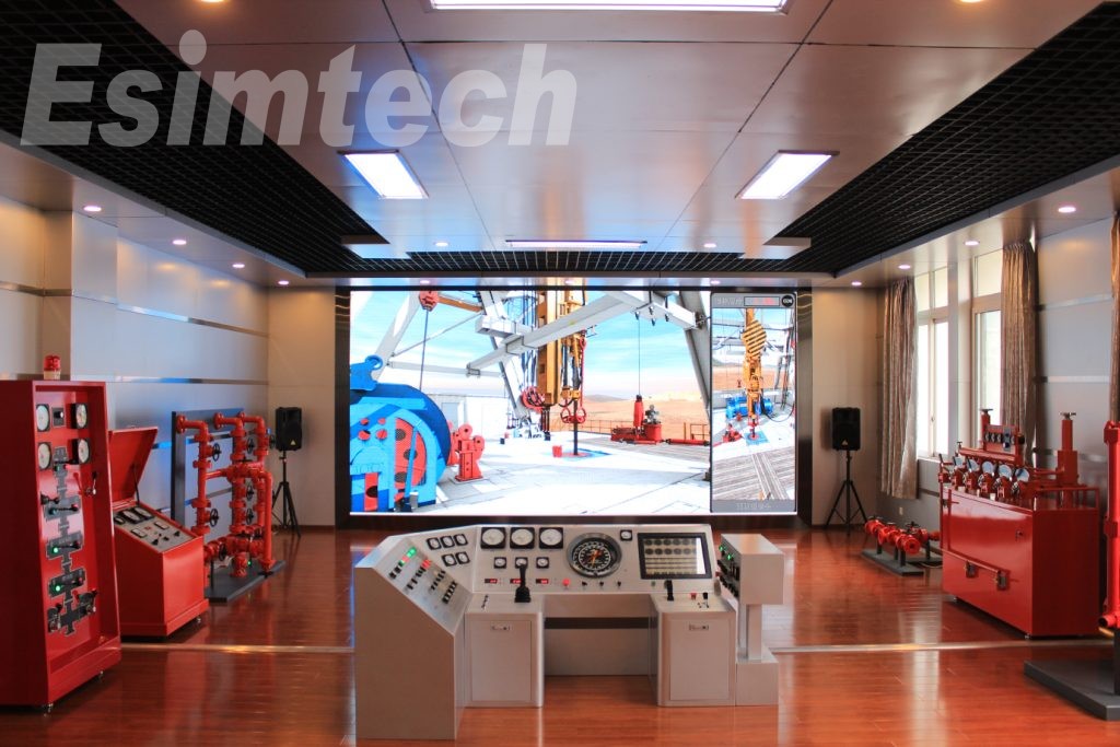
The Role of Simulation Technology in Oil and Gas Exploration and Production
Simulation technology plays a crucial role in the E&P processes, providing valuable insights, enhancing decision-making, and optimizing various operations.
Reservoir Simulation
Reservoir simulation models the behavior of underground reservoirs to better understand fluid flow, pressure changes, and overall reservoir performance. Engineers use these simulations to predict reservoir behavior, optimize production strategies, and estimate ultimate recovery.
Drilling Simulation
Drilling and well control simulations are used to plan and optimize well trajectories, assess drilling risks, and simulate the response of drill strings and downhole tools. These virtual environments allow operators to train personnel, simulate challenging drilling scenarios, and improve overall drilling efficiency and safety.
Production System Simulation
Oil and gas production system simulation models the entire process, from the wellhead to the processing facilities, taking into account variables like flow rates, pressures, temperatures, and fluid compositions. By simulating the entire production system, operators can optimize processes, identify bottlenecks, and improve system efficiency.
Facilities and Processing Plant Simulation
Simulating processing plants and surface facilities is critical for optimizing the separation and treatment of oil, gas, and water. These simulations help design and optimize facility layouts, assess the impact of different processing scenarios, and identify potential issues before construction begins.
Enhanced Oil Recovery (EOR) Simulation
EOR simulation technology is valuable for designing and optimizing the process. By simulating the injection of steam, chemicals, or gases into reservoirs, engineers can predict the behavior of injected substances, optimize injection rates, and maximize oil recovery while minimizing costs.
Risk and Safety Simulations
Simulation is used to assess and mitigate risks associated with various exploration and production activities. Safety simulations help evaluate response protocols and train personnel by simulating emergency scenarios like blowouts or equipment failures, thereby improving readiness and overall safety.
Geological and Seismic Simulations
Simulating geological formations and seismic data helps in understanding subsurface structures and identifying potential hydrocarbon reservoirs. Advanced seismic simulations improve the imaging of subsurface structures, guiding exploration efforts and reducing the uncertainty associated with drilling decisions.
Digital Twin Technology
Digital twin technology involves creating a virtual replica of physical assets or processes. In the oil and gas industry, digital twins are used to monitor, analyze, and optimize operations in real-time, allowing operators to make informed decisions and respond to changes promptly.
Training Simulators
Simulation technology is extensively used for training purposes. Virtual reality (VR) and augmented reality (AR) simulations provide realistic training environments for personnel involved in drilling, production, and safety procedures, helping improve skills, enhance safety awareness, and reduce the learning curve for new technologies.
Data Analytics and Machine Learning
Combining simulation data with analytics and machine learning algorithms enables predictive modeling and optimization. Continuous analysis of simulation and real-time operational data allows companies to identify patterns, optimize processes, and make data-driven decisions, improving overall efficiency.
Conclusion
Oil and gas exploration and production are dynamic processes that demand advanced technologies, interdisciplinary expertise, and a deep understanding of geological and engineering principles. Simulation technology is a powerful tool in the E&P sector, enhancing decision-making, operational efficiency, and safety. As technology advances, the integration of simulations with other cutting-edge technologies is expected to play an even greater role in shaping the future of the oil and gas industry.
The user interface (UI) and usability of web guiding equipment are crucial components in ensuring efficient and precise operations across various industries. This article delves into the significance of user interface and usability in web guiding equipment, emphasizing key design principles and best practices.
Key Design Principles for User Interface in Web Guiding Equipment
The user interface of web guide system equipment significantly impacts the ease of use, operational efficiency, and overall user experience.
Simplicity and Clarity
Intuitive Navigation: The user interface should be designed with a clear and straightforward navigation structure, allowing users to find and access functions effortlessly, without the need for multiple steps.
Minimalism: Avoid overloading the interface with unnecessary elements. Keep screens uncluttered by including only essential components to prevent operator confusion.
Clear Labels: Use concise and unambiguous labels for buttons and controls to minimize misunderstandings and operational errors.
Consistency
Uniform Layouts: Ensure that the layout is consistent across different screens and functions. This helps users predict where to find specific controls or information, reducing the learning curve.
Standard Controls: Utilize standard control elements like buttons, sliders, and icons consistently throughout the interface. Familiar controls contribute to easier system navigation.
Feedback and Responsiveness
Real-Time Feedback: Provide immediate feedback for user actions, ensuring that changes made by the operator are reflected in real-time.
Status Indicators: Incorporate visual indicators, such as color changes, progress bars, or icons, to display the status of operations and highlight any errors or warnings, enabling operators to assess the system’s condition quickly.
Accessibility
Easy-to-Read Fonts: Select legible fonts with appropriate sizing to ensure readability from a distance, avoiding overly stylized fonts that may be difficult to read.
Contrast and Color Use: Maintain sufficient contrast between text and background colors. Use color coding thoughtfully to convey information, while considering color blindness.
Customization and Flexibility
Adaptable Interfaces: Allow users to customize the interface to their preferences or the specific requirements of different tasks. This can include adjusting layouts, changing color schemes, or configuring shortcuts.
Scalable Design: Design the UI to be scalable, adapting to different screen sizes and resolutions, ensuring a consistent user experience across various devices.
Safety and Error Prevention
Error Prevention: Implement features that help prevent errors, such as confirmation prompts for critical actions and input validation to avoid invalid entries.
Emergency Controls: Ensure that emergency stop buttons and clear instructions for handling emergencies are easily accessible and prominently placed.
Training and Support
Integrated Help: Embed help guides and tooltips within the UI to assist users in understanding functions and troubleshooting issues.
Training Modes: Provide a training mode that allows new users to familiarize themselves with the system without affecting actual operations, helping to build confidence and competence.
Performance and Efficiency
Optimized Workflows: Design workflows within the UI to minimize the number of steps required to complete common tasks, enhancing overall productivity.
Loading Times: Ensure that the UI is responsive with minimal loading times, as slow interfaces can frustrate users and impede productivity.
Feedback Collection and Iteration
User Feedback: Regularly gather feedback from operators to identify pain points and areas for improvement, guiding updates and enhancements to the UI.
Continuous Improvement: Continuously refine the user interface based on user feedback and technological advancements, regularly updating it to address emerging needs and incorporate new features that enhance usability.
Best Practices for Usability in Web Guiding Equipment
User-Centered Design
Understand User Needs: Conduct thorough user research to grasp the needs, skills, and limitations of operators, ensuring the design is tailored to their requirements.
Personas and Scenarios: Develop user personas and scenarios to guide design decisions, ensuring the system meets real-world use cases.
Intuitive User Interface
Clear Navigation: Create an intuitive navigation structure that allows users to find information and controls quickly, effectively using menus, tabs, and breadcrumb trails.
Consistent Layout: Maintain a consistent layout across all screens, helping users learn and predict interface behavior.
Effective Feedback Mechanisms
Immediate Feedback: Provide real-time feedback for user actions, using visual or auditory signals when a button is pressed or a setting is adjusted.
Error Messages: Design clear and informative error messages that guide users on how to correct mistakes.
Accessibility and Ergonomics
Readable Fonts and Colors: Use large, legible fonts and high-contrast color schemes to enhance readability, especially in varying lighting conditions.
Ergonomic Controls: Position controls and inputs within easy reach, ensuring they require minimal physical effort to operate.
Customization and Personalization
Adjustable Settings: Allow users to customize interface elements, such as font size, color themes, and layout preferences, to meet their individual needs.
User Profiles: Implement user profiles that save individual settings and preferences, offering a personalized experience.
Streamlined Workflows
Task Automation: Automate repetitive tasks to reduce user workload and minimize the risk of errors.
Guided Processes: Provide step-by-step guidance for complex tasks to ensure web guide systems are completed correctly and efficiently.
Safety and Security
Error Prevention: Design features that prevent common errors in web guide system, such as confirmation prompts for critical actions and input validation to avoid incorrect entries.
Emergency Controls: Ensure that emergency stop buttons and safety controls are prominently placed and easily accessible.
Training and Support
Integrated Help: Include contextual help and tooltips within the interface to assist users in understanding features and troubleshooting issues.
Training Resources: Provide comprehensive training materials, such as manuals, videos, and interactive tutorials, to help users become proficient with the equipment.
Performance Optimization
Responsive Design: Ensure the interface is responsive and performs well under various conditions, as slow response times can frustrate users and hinder productivity.
Efficient Workflows: Optimize workflows to minimize the number of steps required to complete tasks, enhancing overall efficiency.
Continuous Improvement
User Feedback: Regularly collect feedback from users to identify pain points and areas for improvement.
Iterative Design: Implement a continuous process of iteration and improvement based on user feedback and technological advancements.
The user interface and usability of web guiding equipment are pivotal in ensuring effective and safe operations. By focusing on principles like clarity, simplicity, consistency, feedback, responsiveness, and accessibility, manufacturers can develop user-friendly web guide systems that enhance operator performance and minimize errors. Implementing best practices such as user-centered design, comprehensive training, regular updates, customization, and ongoing testing ensures that web guiding control systems remain efficient, reliable, and adaptable to various industrial applications.
Clinical trials are a pivotal phase in the development of new medical treatments, serving as the bridge between laboratory research and real-world patient care. Among the many tools that facilitate this transition, ELISA (Enzyme-Linked Immunosorbent Assay) microplate readers are essential. These devices are invaluable in drug and therapy development, enabling researchers to measure the concentration of specific substances in samples—such as blood—providing critical data on patient progress and the effectiveness of new drugs.
1. Biomarker Discovery and Validation Using ELISA Microplate Readers
3. High-Throughput Screening for Patient Stratification
Patients often respond differently to the same treatment, making it essential to identify subgroups that may benefit more from specific therapies. The high-throughput capabilities of ELISA microplate readers allow for large-scale screening of patient samples, helping researchers stratify participants based on biomarker profiles and tailor treatments to individual needs.
4. Ensuring Data Accuracy and Reproducibility
The accuracy and reproducibility of clinical trial data are critical, and ELISA microplate readers significantly contribute to this reliability. With precise measurement capabilities and standardized protocols, these instruments ensure consistency across multiple sites and studies, bolstering the robustness of clinical findings.
5. Multiplexing: A Comprehensive Approach
Modern clinical trials often require the analysis of multiple biomarkers simultaneously to gain a holistic understanding of a patient’s health. ELISA microplate readers equipped with multiplexing capabilities offer a cost-effective and efficient solution, allowing researchers to assess various biomarkers in a single run.
6. Future Directions and Integration with Precision Medicine
As the field of precision medicine advances, ELISA microplate readers are poised to play an even more significant role in tailoring treatments to individual patient profiles. Their integration with other technologies, such as genomics and proteomics, promises to further personalize clinical trials, leading to more targeted and effective therapies. Future developments may include:
New assays for measuring previously inaccessible biomarkers.
Single-cell analysis capabilities to measure drug concentrations within individual cells.
Real-time biomarker measurement, enhancing the immediacy and relevance of data collected.
Conclusion
ELISA microplate readers have become indispensable tools in the journey from laboratory research to clinical application. Their role in biomarker discovery, treatment monitoring, and patient stratification is crucial to the future of healthcare. As technology continues to evolve, these instruments will be at the forefront of advancing precision medicine and improving patient outcomes in clinical trials and beyond.
Screws are indispensable components across various industries and DIY projects. Whether you’re repairing furniture, assembling machinery, or working on a construction project, accurately measuring screw size is vital. This article provides a detailed guide on how to measure screws, including key measurements and the necessary tools for the task.
How to Determine the Screw Diameter
The diameter of a screw is a crucial measurement, as it represents the distance across the broadest section of its threads. Here’s how to measure it:
Using a Caliper
A caliper is a precision instrument widely used in engineering, woodworking, and metalworking for measuring screw diameter. Here’s how to use it:
Open the Caliper Jaws: Slide the upper jaw away from the lower jaw to fully open the caliper.
Place the Screw Between the Jaws: Insert the screw between the caliper’s jaws, ensuring the jaws make contact with the widest area of the screw’s threads.
Close the Jaws Gently: Slowly close the caliper jaws until they snugly touch the screw, avoiding excessive pressure to prevent deforming the threads.
Read the Measurement: Check the caliper scale or digital display to determine the screw diameter, and note this value for future reference.
Using a Thread Gauge
If you don’t have a caliper, a thread gauge is an alternative tool to measure screw diameter. A thread gauge has various blades or pins, each corresponding to a specific diameter. Here’s how to use it:
Select the Appropriate Blade or Pin: Choose a blade or pin from the gauge that fits snugly into the screw’s threads.
Match the Blade or Pin to the Threads: Insert the selected blade or pin into the screw threads, ensuring no gaps or excessive play.
Determine the Diameter: Read the measurement labeled on the corresponding blade or pin to find the screw’s diameter and take note of this value.
How to Measure the Thread Pitch of a Screw
Thread pitch is the distance between neighboring threads, measured in threads per inch (TPI) for imperial screws or millimeters for metric screws.
Using a Thread Pitch Gauge
A thread pitch gauge is a tool designed to determine the pitch of screw threads. It consists of blades with varying thread pitches. Here’s how to use it:
Align the Gauge: Match the thread pitch gauge blades with the threads of the screw, ensuring they are parallel to the screw’s axis.
Test the Fit: Slide the blades along the threads until one fits snugly, without gaps or forcing.
Read the Measurement: Once the correct blade is found, note the TPI or millimeter measurement labeled on it, representing the screw’s thread pitch.
Using a Ruler
In cases where a thread pitch gauge is unavailable, a ruler with precise increments can estimate thread pitch:
Measure the Distance: Place a ruler alongside the screw threads.
Count the Threads: For imperial screws, count the number of threads within a one-inch span; for metric screws, count the threads within one millimeter.
Calculate the Thread Pitch: Divide the total number of threads by the measured span (one inch or one millimeter) to estimate the thread pitch.
How to Measure the Screw Length
Determining the correct screw length is crucial for ensuring it suits your specific application. Follow these steps to measure screw length:
Place the Screw on a Flat Surface: Position the screw on a flat surface with the head facing upwards, ensuring it’s fully extended.
Align the Ruler or Tape Measure: Place a ruler or tape measure alongside the screw, with the starting point aligned with the screw’s tip.
Measure from the Tip to the Screw Head: Measure the distance from the tip to the bottom of the screw head, keeping the measurement along the central axis of the screw.
Record the Measurement: Note the screw’s length, including both the threaded and unthreaded portions.
If the screw has a countersunk or flat head, measure from the tip to the top of the head rather than the bottom. For very long screws, a carpenter’s square or straight edge can help ensure accurate alignment.
Summary
Accurately measuring screws is essential for ensuring successful installation, compatibility, and overall project success. Proper measurements lead to more efficient and effective screw working, allowing you to make informed decisions when purchasing, replacing, or working with screws in any professional application. By understanding how to measure screw diameter, thread pitch, and length, you can enhance the precision and reliability of your projects.
Workover operations are essential to maintaining the productivity and longevity of oil and gas wells. These operations involve a range of interventions designed to address issues that arise during a well’s production lifecycle, ensuring optimal performance and extending the well’s life. This article delves into the concept of workover operations, provides examples, outlines the steps involved, and underscores the importance of these procedures in the oil and gas sector.
Examples of Workover Operations
Workover operations are diverse, each tailored to address specific challenges within a well. Below are some common examples:
Pump Changeouts:
When a downhole pump, which is critical for a producing well, fails or wears out, workover operations are employed to replace it. Using techniques like coiled tubing, the old pump is carefully removed and a new one is installed, restoring the well’s productivity.
Tubing Changeouts:
Damaged or corroded tubing can obstruct fluid flow and pose safety risks. Workovers involve removing the compromised tubing and installing new, more robust tubing, thereby restoring the well’s efficiency and safety.
Wellbore Cleaning:
Over time, wellbores can become clogged with scale deposits, paraffin buildup, or sand. Specialized tools like high-pressure jetting units or downhole milling tools are used in workover operations to remove these obstructions and ensure smooth production.
Casing Repairs:
Leaks in a well’s casing can be catastrophic, leading to environmental damage and loss of well integrity. Workover operations utilize tools like patchers and cementing equipment to seal these leaks, maintaining the well’s structural integrity.
Artificial Lift Installations:
When natural pressure is insufficient to bring oil and gas to the surface, workover operations install artificial lift systems, such as gas lifts or electric submersible pumps, to boost production from deep reservoirs.
Wellbore Abandonment:
At the end of a well’s life, workover operations ensure its safe and responsible closure. This includes isolating the well from the reservoir, plugging it with cement, and removing surface equipment to prepare the site for future reclamation.
These examples highlight the versatility of workover operations, which are adaptable to the specific needs of each well. Whether it’s restoring production, enhancing safety, or unlocking new reserves, workovers are crucial to the ongoing success of the oil and gas industry.
Steps Involved in Workover Operations
Workover operations are complex and require careful planning, execution, and adaptation. The following steps are typically involved:
Pre-Job Planning:
Data Gathering and Analysis: Engineers review well history, production data, and geological surveys to identify issues and select the most effective tools and technologies.
Simulation and Modeling: Advanced workover operation simulators, anticipating challenges and optimizing equipment deployment, thereby minimizing risks.
Regulatory Compliance: All steps are aligned with safety and environmental regulations, ensuring that permits are obtained and protocols are in place.
Mobilization and Preparation:
Equipment Assembly and Inspection: All tools and technologies are inspected, tested, and assembled at the well site to ensure readiness.
Site Setup and Logistics: A temporary command center is established, complete with communication hubs and emergency response protocols.
Crew Briefing and Safety Training: The crew is thoroughly briefed on the plan, potential risks, and emergency procedures, ensuring a focus on safety.
The Intervention:
Deployment and Monitoring: Tools are deployed into the wellbore, with real-time monitoring by experienced technicians to ensure precision.
Problem-Solving and Adaptation: The crew remains flexible, ready to adapt the plan if unexpected challenges arise during the operation.
Data Collection and Analysis: Continuous data collection allows for real-time adjustments and optimization of the process.
Completion and Post-Job Analysis:
Retrieval and Restoration: Once the operation is complete, tools are retrieved, and the well site is restored to its original condition.
Production Monitoring and Optimization: The well is brought back online, with performance closely monitored and adjustments made to maximize efficiency.
Debriefing and Evaluation: The team reviews the operation, identifying areas for improvement and ensuring continuous learning for future workovers.
These steps provide a flexible framework for workover operations, allowing teams to adapt to the specific requirements of each well and the evolving demands of the industry.
The Importance of Workover Operations
Workover operations are vital to the oil and gas industry, playing a critical role in maintaining and enhancing well productivity. Their importance can be summarized as follows:
Maintaining Production Levels:
Workover operations address issues that could hinder production, such as reservoir changes or equipment failures, helping to sustain optimal production levels throughout a well’s life.
Extending Well Life:
By resolving production issues, workovers can extend the economic life of a well, allowing for maximum hydrocarbon recovery and increased profitability.
Protecting Investment:
Wells represent significant capital investments. Workover operations ensure that wells operate efficiently, optimizing the return on investment by maximizing hydrocarbon production.
Conclusion
In conclusion, workover operations are essential to the oil and gas industry, providing the necessary interventions to maintain, optimize, and extend the life of wells. Through careful planning, advanced technologies, and a commitment to safety, workover operations ensure that wells continue to produce efficiently, protecting the substantial investments made in oil and gas exploration and production. As the industry evolves, the role of workover operations will remain crucial to the success and sustainability of oil and gas wells.
Web guiding systems play a crucial role in industries where continuous rolls of materials such as paper, plastic film, textiles, and metals are processed. By integrating these systems with production lines, businesses can achieve improved product quality, reduced waste, and enhanced operational efficiency. This article delves into the integration of web guiding system equipment with production lines, focusing on the benefits, challenges, and best practices.
Benefits of Integrating Web Guiding Systems with Production Lines
1. Enhanced Product Quality
Consistency: Web guiding systems ensure that web materials remain properly aligned, resulting in uniform and consistent product quality.
Precision: By minimizing defects such as wrinkles, folds, or uneven edges, these systems contribute to a higher quality finished product.
2. Reduced Waste
Material Savings: Accurate alignment reduces material wastage during production.
Operational Efficiency: Fewer defects and misalignments mean less rework and scrap, leading to overall material savings and improved efficiency.
3. Increased Production Speed
Optimized Processes: Precise alignment allows production lines to operate at higher speeds without sacrificing quality.
Reduced Downtime: Continuous monitoring and automatic adjustments help prevent issues that could cause stoppages, thereby enhancing production throughput.
4. Cost Savings
Lower Scrap Rates: Reduced waste and defects directly translate into cost savings on raw materials.
Maintenance: Proper alignment reduces mechanical stress on equipment, lowering maintenance costs and extending machinery lifespan.
5. Improved Efficiency
Real-Time Adjustments: Web guiding systems make real-time corrections to deviations, ensuring smooth and efficient production runs.
Automation: Automated web alignment reduces the need for manual intervention, improving labor efficiency and minimizing human error.
6. Better Control and Monitoring
Data Analytics: Advanced web guiding systems collect and analyze data on web alignment, providing insights to optimize the production process.
Remote Monitoring: Many modern systems offer remote monitoring capabilities, enabling operators to oversee and adjust processes from a distance.
7. Versatility and Flexibility
Multiple Applications: Web guiding systems can be integrated into various production lines, including those processing paper, plastic, textiles, and metals.
Adaptability: These systems can be adjusted to accommodate different materials and production requirements, enhancing the flexibility of the production line.
8. Enhanced Safety
Reduced Manual Handling: Automated adjustments minimize the need for manual intervention, reducing the risk of accidents and injuries.
Compliance: Web guiding systems help ensure compliance with safety standards and regulations, contributing to a safer working environment.
9. Competitive Advantage
Higher Quality Products: Consistent product quality enhances a company’s reputation and market competitiveness.
Efficiency Gains: The overall improvements in efficiency and cost-effectiveness provide a competitive edge in production capabilities and profitability.
Challenges in Integrating Web Guiding System Equipment with Production Lines
1. Compatibility Issues
Legacy Systems: Integrating web guiding systems with older production lines can be challenging due to differences in technology and communication protocols.
Custom Requirements: Unique production line specifications may require tailored integration solutions to ensure compatibility.
2. Calibration and Tuning
Precision Calibration: Accurate calibration of sensors, controllers, and actuators is critical for precise web guiding.
Ongoing Tuning: Regular tuning and adjustments are necessary to maintain optimal performance, requiring specialized knowledge.
3. Training and Skill Development
Operator Training: Comprehensive training is essential for operators to effectively use and maintain new systems.
Technical Expertise: Specialized technical skills are required for integration and troubleshooting, potentially necessitating additional training or hiring.
4. Initial Costs
Investment: The initial cost of purchasing and integrating web guiding systems can be significant.
ROI Calculation: Careful analysis of expected benefits versus upfront and ongoing costs is necessary to determine the return on investment.
5. System Complexity
Integration Complexity: Integrating web guiding systems with existing production lines can be complex, involving coordination between different components.
Troubleshooting: Diagnosing and resolving issues in a complex integrated system can be challenging and require technical expertise.
6. Maintenance and Reliability
Regular Maintenance: Regular maintenance is essential to ensure web guiding systems function correctly, adding to operational costs and potential downtime.
Component Reliability: Ensuring the reliability of all components, such as sensors, controllers, and actuators, is crucial for continuous operation.
7. Environmental Factors
Harsh Conditions: Environmental factors like dust, moisture, temperature fluctuations, and corrosive materials can affect system performance and longevity.
Protection and Durability: Ensuring that web guiding equipment is durable enough to withstand production environments is essential.
8. Data Integration and Management
Data Compatibility: Integrating data from web guiding systems with existing data management systems can be challenging.
Real-Time Processing: Robust and reliable data integration and processing capabilities are required for real-time adjustments.
Scalability: Ensuring that the system can be scaled or modified to accommodate changes in production requirements can be challenging.
10. Safety and Compliance
Safety Standards: Ensuring that the integrated system meets all relevant safety standards and regulations is crucial to avoid legal and operational issues.
Risk of Integration Errors: Integration errors can lead to safety risks, which must be carefully managed through rigorous testing and validation.
Best Practices for Integrating Web Guiding System Equipment with Production Lines
1. Comprehensive Planning
Assessment: Conduct a thorough assessment of the existing production line to identify specific needs and potential challenges.
Customization: Design the integration process to meet the unique specifications of the production line, considering future scalability and flexibility.
2. Collaboration with Experts
Vendor Support: Work closely with web guiding system vendors for proper installation, integration, training, and support.
Consultants: Consider hiring consultants with experience in web guiding system integration for complex projects, and engage with industry experts for tailored insights and best practices.
3. Pilot Testing
Prototype Integration: Implement a pilot test on a small scale to evaluate system performance and make necessary adjustments before full-scale integration.
Feedback Loop: Collect feedback from the pilot test to refine the system and integration process, continuously monitoring performance for iterative improvements.
4. Training and Skill Development
Operator Training: Provide comprehensive training for operators to ensure they understand how to use and maintain the systems, including hands-on sessions and detailed manuals.
Ongoing Education: Encourage continuous learning and skill development to keep pace with technological advancements, offering refresher courses and advanced training modules.
5. Regular Maintenance and Monitoring
Scheduled Maintenance: Implement a regular maintenance schedule to keep systems in optimal condition, performing routine checks on sensors, controllers, and actuators.
Real-Time Monitoring: Use real-time monitoring tools to track system performance and address issues promptly, employing predictive maintenance techniques to anticipate potential failures.
6. Data Integration and Management
Data Compatibility: Ensure that data from web guiding systems is compatible with existing data management systems, using standardized formats and protocols.
Real-Time Processing: Implement robust data processing capabilities to enable real-time adjustments and decision-making, using advanced analytics for system performance insights.
7. Safety and Compliance
Safety Protocols: Establish and enforce strict safety protocols to protect personnel and equipment during the integration process, conducting regular audits and inspections to identify and mitigate potential hazards.
Regulatory Compliance: Ensure compliance with relevant safety standards and regulations, staying updated on industry standards and incorporating best practices to maintain a safe working environment.
8. Continuous Improvement
Feedback and Lessons Learned: Collect feedback and lessons from each integration project to identify areas for improvement, implementing a continuous improvement process that adopts innovative solutions.
Research and Development: Invest in research and development to explore new technologies and techniques for web guiding systems, collaborating with industry partners and research organizations to drive innovation and share knowledge.
Conclusion
Integrating web guiding systems with production lines offers substantial benefits, including enhanced product quality, reduced waste, increased production speed, and cost savings. However, successful integration requires careful planning, addressing compatibility issues, precise calibration, and ongoing operator training. By following best practices and leveraging the expertise of vendors and consultants, manufacturers can effectively integrate web guiding equipment into their production lines, leading to significant improvements in efficiency and quality.
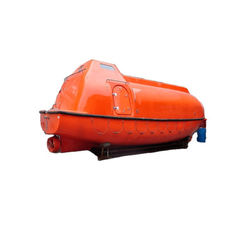
Marine lifeboats are essential safety equipment on ships, designed to ensure the survival of passengers and crew during emergencies. Over the years, advancements in the design of marine lifeboats have significantly enhanced safety, performance in harsh conditions, and deployment speed. These innovations are crucial for meeting international maritime regulations and addressing the evolving challenges faced at sea.
1. Self-Righting Capabilities
Modern lifeboats are equipped with self-righting features that address the vulnerability of traditional lifeboats, which could be capsized by large waves. By incorporating a low center of gravity and buoyant structures, contemporary lifeboats are designed to automatically return to an upright position if overturned. This critical improvement enhances the chances of survival in rough sea conditions.
2. Enhanced Material Durability
The materials used in lifeboat construction have undergone significant advancements. Today’s lifeboats are often constructed from high-strength, corrosion-resistant materials like fiberglass-reinforced plastic (FRP) and advanced composites. These materials not only extend the service life of lifeboats but also minimize maintenance needs. They offer excellent impact resistance, which is crucial for surviving collisions with debris or other vessels during emergencies.
3. Improved Launch and Recovery Systems
Quick and safe lifeboat deployment is vital in emergencies. Innovations in davit systems—used to lower lifeboats into the water—have made this process more reliable and efficient. Modern gravity-based and free-fall davit systems enable rapid deployment, even when the ship is listing or in rough seas. These systems are designed to minimize injury risks during launch, providing a safer and faster escape route for everyone on board.
4. Integrated Communication and Navigation Systems
Once in the water, effective communication and navigation are essential. Modern lifeboats come equipped with integrated communication systems, including VHF radios, Automatic Identification Systems (AIS), and satellite-based distress signaling devices. These systems ensure continuous contact with rescue teams and other vessels, improving the chances of a swift recovery. GPS-enabled navigation systems also help survivors navigate more effectively towards safety.
5. Thermal Protection and Insulation
Exposure to cold water and wind can be life-threatening, especially in polar or deep-sea environments. Innovations in lifeboat design now include enhanced thermal insulation and heat-reflective materials. Some lifeboats feature insulated canopies and integrated heating systems that protect occupants from hypothermia, crucial for improving survival rates in harsh weather conditions.
6. Energy-Efficient Propulsion Systems
Lifeboats are increasingly incorporating energy-efficient propulsion systems to ensure reliable operation over extended periods. Many modern lifeboats use hybrid propulsion, combining traditional diesel engines with electric motors powered by rechargeable batteries. This dual-system approach provides redundancy in case of system failure and reduces fuel consumption and environmental impact. Solar panels are also being integrated into some designs to provide a sustainable energy source for prolonged survival scenarios.
7. Ergonomic and Space-Saving Designs
Comfort and space are vital considerations, especially when survivors may need to remain onboard for extended periods. Innovations in ergonomic seating, optimized interior layouts, and modular storage systems have made modern lifeboats more comfortable and functional. These improvements reduce physical strain on occupants and allow for better organization of emergency supplies and equipment.
8. Smart Technology Integration
The integration of smart technology into lifeboat design is an emerging trend. Lifeboats are now equipped with sensors that monitor critical parameters such as structural integrity, water ingress, and engine performance in real-time. Data from these sensors can be transmitted to the ship or rescue teams, providing valuable information about the lifeboat’s condition and its occupants. Some designs also feature automated self-diagnostic systems that alert the crew to potential issues before they become critical.
9. Environmentally Friendly Features
Sustainability is becoming increasingly important in lifeboat design. Innovations such as biodegradable materials, eco-friendly paints, and energy-efficient systems help reduce the environmental impact of lifeboats. Additionally, advancements in waste management systems ensure that lifeboats remain compliant with environmental regulations, even during emergencies.
Conclusion
Advancements in materials, technology, and structural engineering have led to marine lifeboats that are more durable, reliable, and capable of withstanding harsh conditions. Features like self-righting capabilities, improved buoyancy, and enhanced stability have significantly increased the chances of survival in emergencies. These innovations not only improve the effectiveness of lifeboats but also contribute to safer and more efficient maritime operations.