Splay, a common defect in the injection molding process, refers to the appearance of silver or white streaks on the surface of a molded part. It occurs when gas or vapor becomes trapped within the molten plastic, leaving visible marks as the material solidifies.
Causes of Splay
Moisture content in the resin: Moisture can vaporize during the molding process, forming bubbles that cause splay.
Resin decomposition: Certain resins can decompose at high temperatures, releasing gases that lead to splay.
Contaminated resin: Foreign particles can act as nucleation sites for gas bubbles.
Inadequate resin drying: Moisture in the resin can cause splay.
Injection parameters and mold design: Improper settings or insufficient venting can trap gases.
Material incompatibility: Incompatible materials can produce gases.
Machine and mold contamination: Contaminants can introduce gases into the plastic.
Effects of Splay
Aesthetic defects: Splay can significantly affect the appearance of injection molded parts.
Weakened mechanical properties: Splay can reduce the strength and integrity of parts.
Dimensional inaccuracies: Splay can lead to dimensional variations and assembly issues.
Reduced productivity: Splay can increase scrap rates and downtime.
Increased production costs: Splay can raise costs due to scrap, rework, and quality control efforts.
Impact on brand reputation: Splay can damage a brand’s reputation.
Quality control challenges: Detecting and correcting splay can be difficult.
Preventing Splay
Proper resin selection: Choose resins with low moisture absorption and suitable viscosity.
Resin drying: Thoroughly dry the resin to remove moisture.
Mold design and venting: Ensure adequate venting to allow gases to escape.
Injection parameters: Optimize injection speed, pressure, and temperature.
Cooling system: Use an efficient cooling system to prevent uneven solidification.
Mold maintenance: Regularly clean and maintain the mold.
Gas-assisted injection molding (GAIM): Consider using GAIM to reduce gas pockets.
Quality control and inspection: Implement rigorous quality control procedures.
Advanced technology integration: Machine learning, AI, and high-precision sensors.
Durability and reliability: Long-lasting and low-maintenance.
User-friendly interface: Easy operation and quick adjustments.
By implementing these strategies and considering the Arise web guide system, industries can effectively mitigate vibration and ensure precise web guiding.
Printing quality inspection is essential for maintaining the highest standards in print production, ensuring that printed materials meet the expectations for color accuracy, image quality, text clarity, and overall appearance. With technological advancements, the printing industry has access to sophisticated tools used for printing quality inspection with remarkable precision and efficiency.
Camera-Based Systems: These high-speed systems capture detailed images of printed products. The software analyzes the images to detect defects like misalignment, smudges, or color deviations. The system’s real-time integration allows for immediate detection and correction.
Line Scan Cameras: These cameras inspect continuous or large-format prints, like packaging or wallpaper, capturing images line by line for precise analysis.
Machine Vision Systems
Deep Learning Models: AI-driven deep learning models can identify a wide range of defects and improve accuracy over time. They can detect subtle issues that traditional systems may overlook.
Pattern Recognition: Machine vision systems are programmed to recognize specific patterns and detect anomalies, which is particularly useful in industries that demand precise image reproduction and color matching.
Spectral Imaging Systems
Hyperspectral Imaging: Captures a wide range of wavelengths, from ultraviolet to near-infrared, identifying subtle color and material inconsistencies.
Multispectral Imaging: Focuses on multiple wavelengths to analyze color and material data, useful in detecting material defects though less comprehensive than hyperspectral imaging.
3D Inspection Systems
Laser Profiling: These systems use lasers to scan surfaces and create 3D maps, detecting embossing errors and surface irregularities.
Structured Light Scanning: Projects light patterns onto the surface, analyzing deformations to build a 3D image for surface texture analysis.
Magnetic and Conductive Inspection
Magnetic Ink Character Recognition (MICR): Used in security printing, such as checks and banknotes, to verify the magnetic properties of printed inks for authenticity.
Conductive Ink Inspection: Ensures that printed circuits and electronic components have correct electrical properties, which are critical for printed electronics like RFID tags.
Why Choose Arise Web Video Inspection System for Printing Quality Inspection?
Arise is a high-tech company specializing in optical, electromechanical, electronic, and internet technologies, particularly in the development of web guide systems, tension control systems, and web inspection systems.
The Arise Web Video Inspection System uses innovative technology to transform rapidly moving images into still frames, which are magnified for detecting print defects. The system allows real-time observation and provides comprehensive quality assessments for immediate defect detection.
Key Benefits of Arise Web Video Inspection System
High-Resolution Imaging: Captures minute details to identify even the smallest defects in real-time.
Real-Time Monitoring: Enables continuous monitoring of the printing process, allowing immediate issue detection and correction, which minimizes waste and increases efficiency.
Automated Defect Detection: Advanced algorithms automatically identify defects like color variations, misregistration, and print artifacts, reducing the need for manual inspection.
Consistent Quality Control: Ensures uniform quality by applying objective and automated inspection criteria, minimizing the variability caused by human inspection.
Data Collection and Analysis: The system tracks defect types and frequencies, providing valuable data for improving the printing process and conducting root cause analysis.
Workflow Integration: The system seamlessly integrates into existing printing workflows, enhancing efficiency without disrupting production.
User-Friendly Interface: Simplifies operation, making the system accessible to operators with varying levels of technical expertise.
Cost-Effective: By automating inspection and reducing rework, the system offers significant cost savings.
Compliance and Standards: Helps meet industry standards and customer specifications, essential for maintaining reputation and customer trust.
Scalability: Adaptable to different production scales, from small print runs to large-volume operations.
Conclusion
The adoption of advanced technologies in printing quality inspection, such as the Arise Web Video Inspection System, enables businesses to achieve higher quality outputs while optimizing efficiency and reducing costs. With features like real-time monitoring, automated defect detection, and seamless integration, this system is an ideal solution for industries seeking superior printing quality and operational excellence.
Ethanol, a versatile solvent used in various industries, is often extracted from solutions through evaporation. A rotary evaporator, a specialized piece of laboratory equipment, is a highly efficient and effective tool for this process.
What is a Rotary Evaporator?
A rotary evaporator consists of a round-bottom flask that rotates continuously while submerged in a heated water bath. This rotation creates a thin film of the solution on the flask’s inner walls, increasing the evaporation surface area. A vacuum pump is connected to the system, lowering the boiling point of the solvent, typically ethanol, to a temperature significantly below its atmospheric boiling point. This gentle evaporation process minimizes the risk of damaging heat-sensitive compounds in the extract.
Why Use a Rotary Evaporator for Ethanol Extraction?
Traditional evaporation methods, such as open-air boiling, have several drawbacks:
High temperatures: Can damage heat-sensitive compounds in the extract.
Ethanol loss: Significant amounts of ethanol can be lost to the atmosphere.
Difficult control: Manual control of the evaporation process can lead to inconsistent results.
In today’s rapidly evolving oil and gas industry, effective data management is essential for optimizing operations, ensuring compliance, and making informed strategic decisions. As the volume and complexity of data increase, specialized oil and gas saoftware solutions play a crucial role. This article explores the significance of these software tools, their key features, and the benefits they offer to the industry.
The Challenges of Oil and Gas Data Management
The oil and gas industry generates vast amounts of data from exploration, production, refining, and distribution. This data includes geological surveys, well logs, production volumes, equipment statuses, and more. Managing this data effectively presents significant challenges, including:
Data volume: The sheer volume of data can be overwhelming.
Data variety: Data comes from various sources and formats, making integration difficult.
Data quality: Ensuring data accuracy and reliability is critical.
Real-time needs: The industry requires real-time access to data for operational efficiency.
Predictive analytics: Forecasts equipment failures, production trends, and market dynamics.
Collaboration and workflow management: Facilitates teamwork and streamlines processes.
Benefits of Oil and Gas Data Management Software
Improved decision-making: Data-driven decisions lead to better outcomes. The drilling and well control simulator which adopts advanced data analysis software, can collect and analyze drilling data, providing real-time feedback on drilling performance and safety.
Cost reduction: Optimizes operations, reduces downtime, and improves efficiency.
Enhanced safety and compliance: Ensures adherence to safety regulations and minimizes risks.
Increased productivity: Streamlines workflows and reduces manual tasks.
Optimized exploration and production: Leverages data to improve upstream operations.
Adaptability to market changes: Enables companies to respond to market fluctuations.
Conclusion
In the competitive oil and gas industry, effective data management is essential for success. By leveraging specialized software solutions, companies can overcome the challenges of data management, optimize operations, improve decision-making, and ensure long-term sustainability. As the industry continues to evolve, the importance of data management will only grow.
Drilling into a stud is a fundamental skill for any DIY enthusiast or homeowner. It ensures a secure and durable attachment for items like shelves, mirrors, and TV mounts. Here’s a detailed guide to help you do it safely and effectively.
Tools and Materials
Stud finder
Pencil or marker
Power drill
Appropriate drill bit
Tape measure
Level
Masking tape
Locating the Stud
Scan the wall: Use a stud finder to locate the stud. Most stud finders emit a sound or light when they detect a stud.
Mark the edges: Mark the edges of the stud with a pencil or marker.
Verify width: Slide the stud finder horizontally to confirm the stud’s full width.
Measuring and Marking the Drilling Point
Determine the mounting location: Choose the desired spot for your item. Use a level to ensure it’s straight.
Measure the height: Measure the distance from the floor or a reference point to the desired center of your item.
Find the stud center: Locate the middle of the stud based on your measurements.
Mark the drilling point: Make a small mark on the wall. For better visibility, use a pencil on light walls and a marker on dark ones.
Double-check measurements: Verify your measurements and markings.
Consider offsetting: For heavier items, consider drilling slightly off-center, closer to the stud’s edge, for increased stability.
Apply masking tape: Place a small piece of masking tape over the drilling site to prevent wall damage.
Drilling the Hole
Insert the drill bit: Choose the appropriate drill bit based on the screw types you’ll be using.
Start drilling: Place the drill bit precisely on the mark and begin drilling at a medium speed.
Check depth: Use a piece of tape wrapped around the drill bit as a depth gauge to avoid over-drilling.
Insert the screw or anchor: Once the hole is drilled, insert the screw or anchor.
Safety Tips
Wear safety glasses: Protect your eyes from potential debris.
Avoid electrical wires: Use a stud finder that can detect live wires to prevent accidents.
Hold the drill firmly: Maintain a secure grip on the drill to prevent it from slipping.
By following these steps and prioritizing safety, you can confidently drill into a stud for a secure and reliable installation.
In today’s fast-paced printing industry, maintaining high standards of quality is paramount. Any deviation can lead to costly reprints, customer dissatisfaction, and damage to a brand’s reputation. Integrating quality inspection systems seamlessly into printing workflows has become essential to ensure every product meets the highest standards. This article explores the importance of this integration, the technologies involved, the benefits it brings, and the challenges it faces.
The Importance of Quality Inspection
Quality inspection in printing ensures that each product meets predefined standards before reaching the customer. It involves checking for color consistency, print accuracy, material defects, and other critical factors. While traditional manual methods are still used, automated systems offer greater accuracy and efficiency.
Technologies Enabling Seamless Integration
Seamless integration relies on a combination of advanced technologies:
High-Resolution Cameras and Sensors: Capture detailed images and data for precise defect detection.
Machine Learning and Artificial Intelligence: Analyze data, identify patterns, and improve over time.
Real-Time Data Processing: Enable immediate defect detection and correction.
Interoperable Software Platforms: Facilitate communication between printing machinery and inspection systems.
Data Security: Protecting sensitive data generated by inspection systems is crucial.
Training and Skill Development: Operators may need training to effectively use and maintain these complex systems.
Integration Complexity: Integrating different systems and technologies can be challenging.
Conclusion
The seamless integration of quality inspection systems with printing workflows is essential for maintaining high standards, improving efficiency, and achieving a competitive advantage. By leveraging advanced technologies, companies can ensure that their products consistently meet customer expectations and regulatory requirements.
Rubber fenders play a crucial role in safeguarding ships and marine infrastructure from the harsh impacts that occur during docking and mooring operations. Advancements in design and material engineering have significantly enhanced the performance and durability of these essential components.
What are Rubber Fenders?
Rubber fenders are protective devices designed to absorb the kinetic energy of a vessel during berthing, preventing damage to both the ship and the dock. They are widely used in ports, harbors, and offshore platforms. These fenders are constructed from high-quality rubber, making them resistant to environmental factors such as UV radiation, abrasion, and chemical exposure. The shape and size of rubber fenders can vary to accommodate different vessel sizes, berthing velocities, and angles.
Common Types of Rubber Fenders
Cylindrical Fenders: These versatile fenders are simple in design and offer good energy absorption.
D-Shaped Fenders: Ideal for mounting on docks and ships, D-shaped rubber fenders provide moderate energy absorption and are space-efficient.
Cone Fenders: Known for their high energy absorption and low reaction force, cone fenders are suitable for large vessels and harsh conditions.
Arch Fenders: With a curved design, arch fenders offer excellent durability and resistance to high loads.
Cell Fenders: Highly efficient in energy absorption, cell fenders are often used for large vessels and provide excellent stability.
Key Advancements in Rubber Fender Design
Advanced Material Technology: Modern rubber fenders incorporate high-performance elastomeric compounds that enhance strength, flexibility, and resistance to wear and tear. These materials improve durability and reduce maintenance needs.
Enhanced Energy Absorption: Innovative designs and internal reinforcement techniques optimize energy absorption and load distribution, minimizing deformation and extending the service life of fenders.
Modular and Customizable Designs: Modular fender systems allow for easier maintenance and customization to meet specific vessel types and docking conditions.
Sustainability and Recyclability: The focus on sustainability has led to the development of recyclable and biodegradable materials, reducing the environmental impact of rubber fenders.
Smart Fender Technology: The integration of sensors and smart technology enables real-time monitoring of impact forces, wear levels, and overall performance, facilitating maintenance and improving operational efficiency.
Pneumatic and Hybrid Fenders: Pneumatic and hybrid fenders offer additional flexibility and adaptability, particularly for offshore applications.
Conclusion
The design of rubber fenders has evolved significantly, incorporating advancements in materials, energy absorption, modularity, sustainability, and smart technology. These innovations ensure that marine rubber fenders remain reliable, adaptable, and efficient in protecting vessels and port infrastructure. As technology continues to advance, we can expect even more innovative solutions to enhance the performance and sustainability of these critical components.
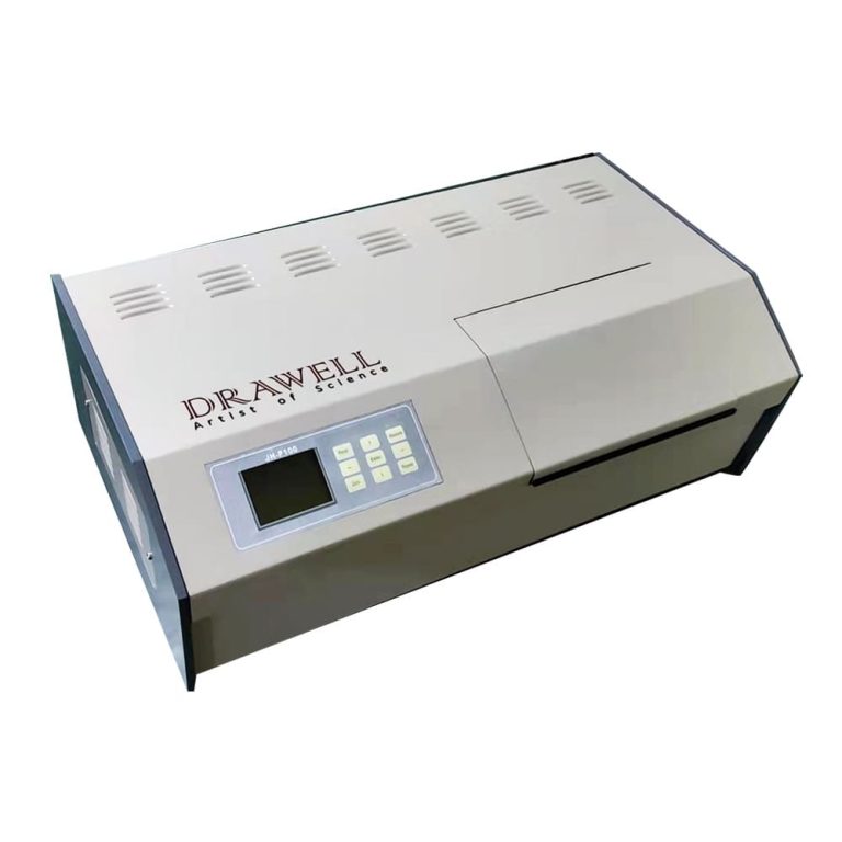
Automatic polarimeters are indispensable tools for measuring optical rotation, a property exhibited by chiral compounds. Chirality refers to molecules that are non-superimposable mirror images of each other. These instruments are widely used in various industries, including pharmaceuticals, food and beverage, and chemical analysis.
How Automatic Polarimeters Work
The working principle of automatic polarimeters revolves around the interaction of polarized light with chiral substances. A monochromatic light source generates a polarized light beam, which is then passed through a sample chamber containing the chiral compound. As the polarized light interacts with the sample, its plane of polarization rotates. This rotation is measured by an analyzer and converted into specific optical rotation values.
Key Components and Functions
Light source: Generates a polarized light beam.
Polarizer: Converts unpolarized light into polarized light.
Sample chamber: Holds the chiral sample.
Analyzer: Measures the rotation of the plane of polarization.
Detector: Detects the intensity of the transmitted light.
Data analysis: Calculates specific optical rotation values based on the measured rotation.
Applications of Automatic Polarimeters
Pharmaceutical Industry: Used to determine the purity and concentration of chiral compounds in pharmaceutical formulations.
Food and Beverage Industry: Analyzes sugars, sweeteners, and other chiral substances in food products.
Chemical Analysis: Studies the composition and behavior of chiral molecules in organic synthesis and stereochemistry.
Advantages of Automatic Polarimeters
High precision: Delivers accurate and reliable measurements.
Time efficiency: Automation speeds up the measurement process.
Ease of use: User-friendly interface for operators of all levels.
Data management: Facilitates record-keeping and analysis.
Conclusion
Automatic polarimeters are essential tools for analytical science, offering precise and efficient measurements of optical rotation. Their applications extend across various industries, contributing to product quality, research advancements, and a deeper understanding of chiral compounds. As technology continues to evolve, automatic polarimeters are likely to play an even more pivotal role in the future of analytical chemistry.
A jack-up rig, or self-elevating unit (SEU), is a mobile offshore drilling platform designed to operate in shallow water depths. It’s equipped with retractable legs that can be lowered onto the seabed, elevating the rig above the water’s surface. This unique design allows it to access areas inaccessible to other drilling platforms.
Key Features and Advantages
Versatility: Jack-up rigs can be quickly mobilized and deployed to various locations, making them ideal for short-term projects or exploring new prospects.
Cost-effectiveness: Compared to fixed platforms, jack-up rigs have lower construction and installation costs, making them more economical for shallow water drilling.
Safety: Their elevated position provides a stable and safe working environment for crew members, even in rough sea conditions.
Accessibility: Jack-up rigs can access shallower areas than other platforms, unlocking previously untapped reserves.
Types of Jack-up Rigs
There are several types of jack-up rigs, each with its own unique design and capabilities:
Independent Leg Jack-up Rigs: This is the most common type, featuring three or four independent legs that are lowered individually onto the seabed.
Mat-Supported Jack-up Rigs: These rigs incorporate a large mat foundation to distribute the weight more evenly, making them suitable for softer seabed conditions.
Caisson-Supported Jack-up Rigs: This design uses large hollow structures called caissons for additional stability and lifting capacity, making them ideal for deeper waters and harsh environments.
Slot Jack-up Rigs: These rigs feature a slot in the platform deck for drilling operations, allowing for more efficient drilling, particularly for directional and horizontal wells.
Cantilever Jack-up Rigs: With a drilling derrick mounted on an extending arm, these rigs can drill beyond the footprint of the platform, offering greater flexibility for well positioning.
Functions of Jack-up Rigs
Jack-up rigs are versatile platforms used for a variety of offshore activities, including:
Exploration drilling: Discovering new oil and gas reserves in shallow waters.
Development drilling: Extracting discovered reserves.
Well completion and workover: Installing production equipment and maintaining wells.
Decommissioning: Removing old platforms and pipelines.
Accommodation and support: Providing living quarters and logistical support for offshore personnel.
Scientific research: Supporting research activities in marine science and oceanography.
The Role of Simulation
Simulation technology has revolutionized jack-up rig drilling. It offers immersive training for critical procedures like well control and emergency response, reducing the risk of accidents. By optimizing drilling processes beforehand, drilling simulation system minimizes downtime and improves efficiency, leading to faster completion times and cost savings.
As technology advances, oil and gas simulation tools will continue to play a crucial role in enhancing training effectiveness and operational efficiency for jack-up rigs, ensuring the success of offshore drilling projects and shaping the future of this vital industry.