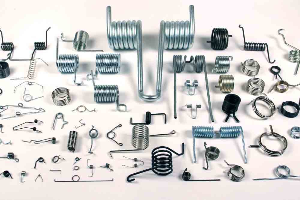
Surface treatment is a process method, which refers to the artificial formation of a surface layer on the surface of the substrate material with different mechanical, physical, and chemical properties from the substrate. The purpose of surface treatment is to meet the requirements of product wear resistance, corrosion resistance, decoration, and so on.
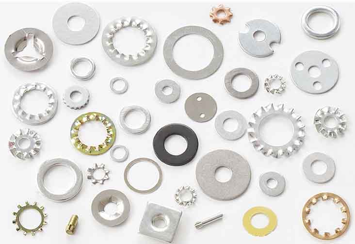
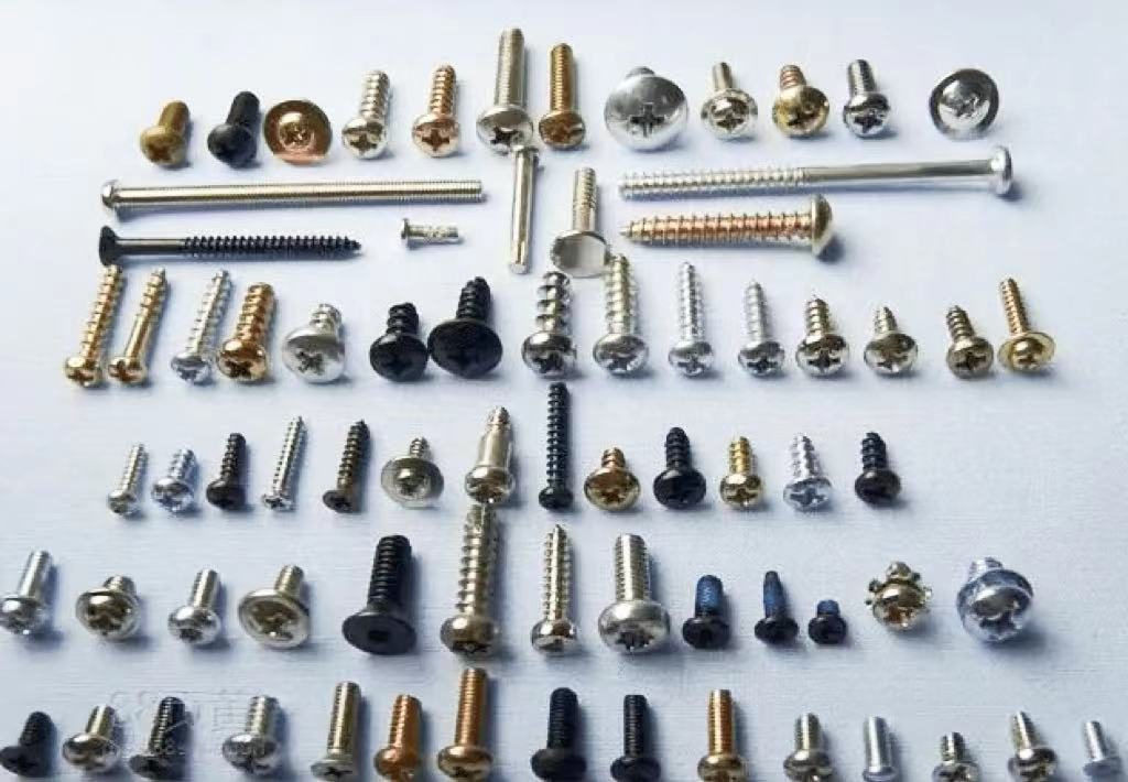
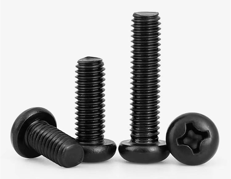
In the selection of screws, in addition to the main consideration, the color of the appearance and corrosion resistance should also be considered. Common surface treatment processes for screws include oxidation, electrophoresis, electroplating, dacromet, and so on.
Black Oxidation Treatment
Black oxidation treatment is a common method of chemical surface treatment, the purpose is to produce an oxide film on the metal surface to isolate the air and prevent rust.
The process is to use a strong oxidant to oxidize the surface of the steel into dense and smooth ferroferric oxide. This thin layer of ferroferric oxide can effectively protect the inside of the steel from oxidation. Divided into low temperature and high temperature.
Ferroferric oxide formed at low temperatures (about 350°C) is dark black, also known as blackening. Ferroferric oxide formed by oxidation at high temperatures (about 550°C) is sky blue, also known as bluing treatment. The blue treatment is commonly used in weapon manufacturing, and the black treatment is commonly used in industrial production.
Oxidizing the steel surface to dense, smooth ferroferric oxide requires a strong oxidant. The strong oxidant is composed of sodium hydroxide, sodium nitrite, and trisodium phosphate. When it turns blue, treat the steel with a strong oxidant melt, and when it turns black, treat it with an aqueous solution of a strong oxidant.
Electroplating
Electroplating is the process of using electrolysis to coat a layer of other metal films or alloy films on the metal surface. The purpose is to improve wear resistance, corrosion resistance, and aesthetics.
There are 2 types of black plating: black zinc plating and black nickel plating.
Black zinc plating is a kind of anti-oxidation processing of metal, which is suitable for hardware products. Zinc is chemically active and easily oxidized and darkened in the atmosphere. After galvanizing, it is treated with chromate to cover a chemical conversion film on the zinc, so that the active metal is in a passive state, which is the passivation treatment of the zinc layer. The passivation film can be divided into white passivation (white zinc), light blue (blue zinc), black passivation (black zinc), green passivation (green zinc), etc.
Usually, the process of electroplating black zinc is degreasing-cleaning-weak acid etching-electro-galvanizing-cleaning-passivation-cleaning-drying-sealing paint.
The black nickel coating obtained from the black nickel bath contains 40-60% nickel, 20-30% zinc, 10-15% sulfur, and about 10% organic matter. The black color is caused by the presence of black nickel sulfide in the coating due to the reduction of thiocyanate on the cathode to release sulfide ions. The copper bottom is added in the process, and the main function is to make nickel plating easier in the post process and to improve the corrosion resistance of the screw.
Electrophoresis
Electrophoresis refers to the phenomenon in which charged particles move toward electrodes of opposite electrical properties under the action of an electric field.
Black electrophoresis is the use of an external electric field to make particles such as pigments and resins suspended in the electrophoresis solution directionally migrate and deposit on the substrate surface of one of the electrodes. Electrophoretic black is widely used in the industry, taking the black process as an example: degreasing – cleaning – phosphating – electrophoretic paint – drying. It can be divided into anodic electrophoresis (resin becomes negative ions after ionization) and cathodic electrophoresis (resin becomes positive ions after electrophoresis). Compared with the painting process, it has better construction performance, less pollution and harm to the environment and its resistance to neutral salt spray is 300 hours or more, and the cost and corrosion resistance are similar to those of the dacromet process.