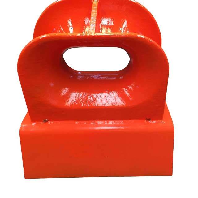
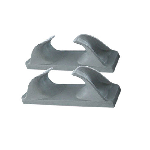
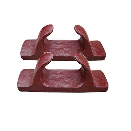
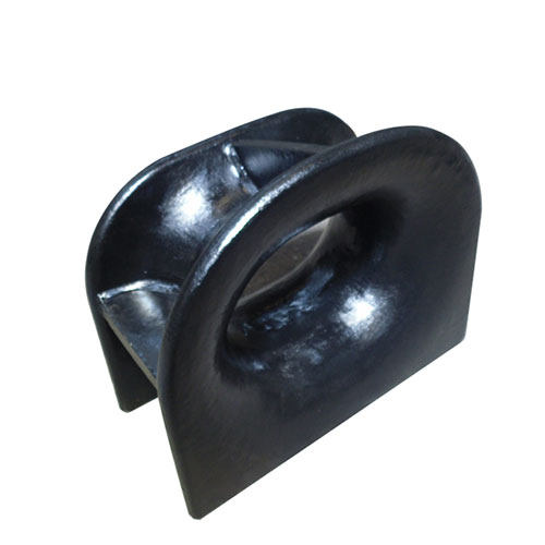
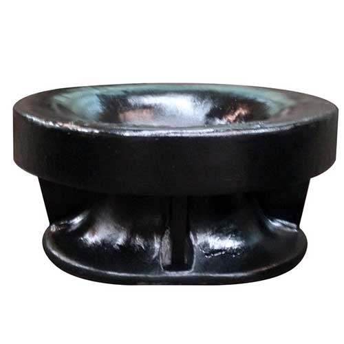
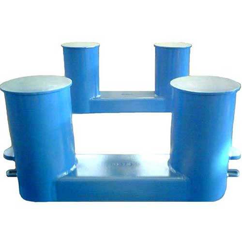
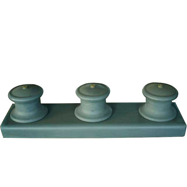
A roller fairlead is a mechanical device used in the maritime industry to guide ropes or cables while reducing friction. It is frequently made up of a number of rollers or sheaves that are fastened to a frame or structure and arranged in a certain arrangement to guide ropes or cables smoothly and evenly.
Function Of A Roller Fairlead
The key function of a roller fairlead is to guide ropes or cables in a controlled manner, eliminating the possibility of friction, wear, and damage. A roller fairlead reduces resistance during movement by providing a smooth and properly aligned passage for the ropes or cables, resulting in improved efficiency and less wear on the ropes or cables.
Roller fairleads are used in many industries, including maritime and offshore, construction, transportation, and other heavy-duty enterprises that require ropes or cables for lifting, towing, or other operations. Winches, cranes, hoists, towing systems, and other pieces of equipment that require the controlled movement of ropes or cables are common places to find them.
Benefits Of Using Roller Fairleads In Load Handling Operations
Reduced friction and wear
Roller fairleads reduce friction and wear by providing a smooth and controlled path for ropes or cables during movement. This increases rope and cable longevity by decreasing abrasion and damage caused by rubbing against sharp edges, corners, or rough surfaces.
Improving efficiency
Marine roller fairleads enable the smooth and even movement of ropes or cables, lowering resistance and increasing load handling efficiency. This can result in speedier and more efficient processes, as well as less downtime and higher productivity.
Enhancing safety
Roller fairleads reduce the danger of accidents and injuries during load handling operations by directing ropes or cables in a controlled manner, reducing the possibility of unexpected jerks or snags. Ropes and cables that are properly aligned and tensioned also reduce the potential of dangerous rope or cable breakdown.
Versatility
Roller fairleads are versatile and adaptable to a wide range of load handling requirements since they can be used in a variety of applications and industries. They can be used on a wide range of equipment, such as winches, cranes, hoists, towing systems, and so on.
Consistency in load handling
Marine roller fairleads maintain perfect alignment and tension on ropes and cables, allowing for more consistent weight handling activities. This can improve load handling precision and accuracy, reducing the possibility of weight shifting or unequal distribution.
Factors To Consider When Selecting A Roller Fairlead
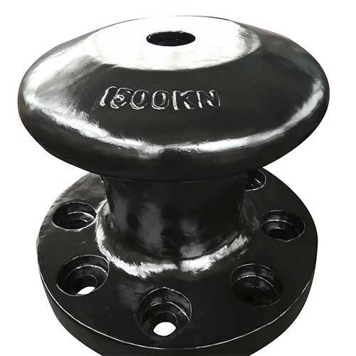
Load capacity
The roller fairlead’s load capacity should be sufficient to handle the maximum load imparted to the ropes or cables during the load handling activity. To ensure safe and dependable operation, it is necessary to examine both static and dynamic loads and select a roller fairlead with an adequate load rating.
Rope or cable size
The roller fairlead should be compatible with the size and kind of rope or cable used in the weight handling operation. Examine the diameter, construction, and substance of the ropes or cables when selecting a roller fairlead to ensure a proper fit and smooth movement.
Mounting arrangement
The installation arrangement for the roller fairlead should be compatible with the equipment or structure where it will be installed. Consider the available space, mounting options (e.g., horizontal, vertical, angled), and the structural soundness of the mounting arrangement to ensure safe and secure installation.
Roller or sheave configuration
The rollers or sheaves on the roller fairlead should be configured specifically for the task. Consider parameters such as the number of rollers or sheaves, their spacing, and alignment. to ensure proper rope or cable guidance and to reduce friction during movement.
Material and construction
The material and structure of the roller fairlead should be appropriate for the environment and conditions in which it will be used. Factors such as corrosion resistance, durability, and maintenance requirements should be considered to ensure long-term performance and reliability.such as the number and spacing of rollers or sheaves.
Safety features
The roller fairlead should incorporate suitable safety elements such as guards, covers, or locking mechanisms to avoid accidental disengagement or entanglement of ropes or cables during operation. Safety elements should be in conformity with relevant industry norms and laws to ensure safe operation.
Manufacturer reputation and support
Consider the roller fairlead manufacturer’s reputation and support. Look for reputable manufacturers with a track record of producing dependable and high-quality roller fairleads, and ensure that they provide adequate technical support, documentation, and after-sales service.