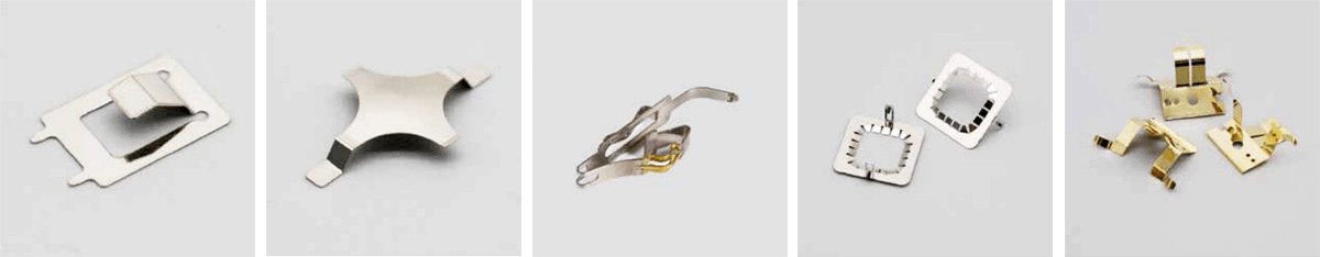
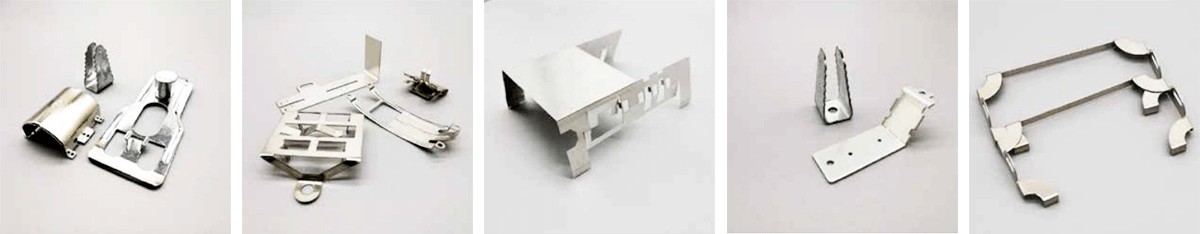
Metal stamping is the process of deforming or breaking stainless steel, iron, aluminum, copper, and other plates and other materials with punches and dies to obtain a specific shape and size. It entails stretching and blanking the metal plate in two or three dimensions. Perforation and other operations can also be used in the metal stamping process.
The following glossary defines common technical words used in metal stamping parts.
1. Deep drawing: A stamping process that converts raw steel or process parts into hollow parts or changes the shape and size of hollow parts. The flow of material outside the bottom of the punch into the die mostly forms the hollow part during deep drawing.
2. Trimming: A stamping procedure in which the forming process’s edge is trimmed with a metal stamping die to have a specific diameter, height, or shape.
3. Punching: A punching technique that separates waste from the material or process piece along the closed contour and creates the desired hole in the material or workpiece.
4. Flanging: A stamping procedure that turns the material into a short side that stands on the side of the contour curve.
5. Flipping hole: A stamping procedure in which the material is transformed into a side flange around the inner hole’s circle.
6.Blanking is a stamping technique used to separate materials along a closed outline. The separated material becomes a workpiece or process piece, most of which are flat.
7. Shaping: a stamping technique that uses material flow to adjust the shape and size of process parts in a small amount to assure workpiece precision.
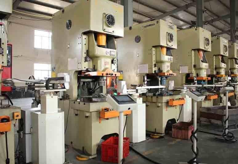
When compared to CNC machining, stamping is a relatively inexpensive and quick method of production. Metal stamping is the ideal choice when speed is the most important factor. CNC machining, on the other hand, is more advantageous when complicated or high-precision forms are required.
Introduction of CNC Machining
CNC machining is a method of machining that employs digital data to control the displacement of parts and equipment. It is appropriate for a variety of parts, small batches, complex shapes, and high precision.
Axis motion driven by a spindle is included in CNC machine tools. A device may contain many spindles that receive computer program instructions to direct each spindle to the appropriate geometry.
CNC machining can provide
High tolerance precision.
Excellent surface polish and bespoke treatments are available.
Even with huge production, repeatability is important.
What Factors Should Be Considered Prior to Choose CNC Machining or Stamping?
Processing Volume
Metal stamping is suited for high-volume production, whereas CNC machining is ideal for low-volume production.
Price
CNC machining is expensive, whereas stamping is quite inexpensive.
Capacity for Production
Metal stamping provides a better production capacity, faster speed, and a broader application than CNC machining. While it takes time to prepare a punch for production, when properly set up, it can run efficiently and effectively.
Production Speed
Metal stamping is the most efficient method of producing metal shapes. When the production line is working normally, it produces at a high rate. However, metal stamping cannot produce the complicated, high-precision pieces that CNC machining can. Stamped items may require extra processing before usage in order to meet greater precision requirements.
Manufacturing Precision
CNC machining offers great precision, and it serves a variety of manufacturing businesses since its technology is dependable and efficient. CNC machining is the preferred method for advanced components requiring tight tolerances and high.
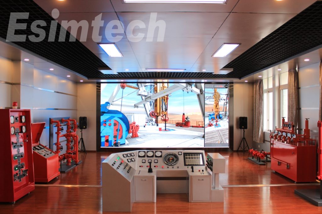
The status of diverse oil wells and oilfields has become more complex as oil and gas development has progressed, and the hazards faced by the construction site have increased. The drilling and well control simulation system has been widely used for drilling technician experimentation, training, and evaluation. Traditional field training is constrained by the location and ocular aspect, and the training impact is suboptimal. VR virtual reality technology is an excellent tool for drilling well control training.
VR virtual reality technology works with 3D interactive equipment to simulate the well site environment, equipment and facilities, operators, and work processes, as well as the formation structure, borehole trajectory, drilling targets, and other objects that can be seen with the naked eye, and the display effect is accurate, intuitive, and diverse. Reduce the design cost and development cycle significantly.
Why Should You Use a Drilling And Well Control Simulation System?
The drilling and well control simulation system completely covers the knowledge and theory of numerous disciplines, types of work, and equipment used in system engineering, and the teaching system is thorough. Students are not required to take precise measurements of the abandoned oil fields.
The virtual reality system communicates with external handheld devices to display the structure through dynamic viewing, moving, rotating, and scaling actions. The work cycle is primarily illustrated by video and audio.
In comparison to offline training, simulator training is not limited by space or time as it may be carried out by attending a virtual classroom online. It also sets clear and consistent training evaluation standards, which supports unified management. Furthermore, through virtual and realistic scene simulation, online training methods can realize some related dangerous procedures and some advanced training that are difficult to achieve in offline training.
The device also activates the downhole accident mode to imitate the actual process caused by incorrect operation. To expand their study of safety principles and emergency measures, trainees can receive timely error prompts and feedback on training results.
Furthermore, teachers can train numerous students at the same time, saving resources. After completing their study, students can conduct post-class consolidation reviews at any time.
Handling emergencies necessitates the seamless coordination of all links, in addition to training personal practical operation competence. The VR virtual reality remote information sharing system, developed in conjunction with the Internet, spans workshops and departments, allowing for multi-user engagement and collaboration, and significantly increases the effectiveness of department collaboration, workflow mode, and sharing mode. A relationship between the online simulator training system and the offline training system is not required.
Drilling and Well Control Simulation System Applications
Drilling and well control simulation applications include rig installation, well logging, oil and gas gathering and transportation, fracturing and acidizing, coiled tubing, oil and gas production, transportation, downhole operations, emergency exercise simulator, and other areas, with a wide range of 3D oil & gas animations, such as drilling and well control equipment disassembly and working principle animation.
Drilling and well control simulation systems make extensive use of 3D technologies.
3D simulation, 3D interaction, and other technologies are utilized to provide realistic simulation and 3D interaction of drilling drill scenes, human situations, equipment and facilities, and environmental conditions.
These simulation training systems can automatically work with trainers to complete various exercise programs, have realistic settings, and provide an excellent user interaction experience thanks to virtual reality technology.
Workflow of Drilling and Well Control Simulation System
1.The initial phase is to design and configure the Drilling and Well Control Simulation System. This often entails selecting and setting the right simulators, control panels, and computer systems to model the desired drilling situations and circumstances.
2.Operator training: After the Drilling and Well Control Simulation System is installed, operators are trained to use the simulator and control panel. Drilling techniques, well control, and emergency response procedures are often covered in this training.
3.Simulation: After installing the Drilling and Well Control Simulation System and training operators, simulations can commence. Operators improve their skills and tactics by manipulating the simulator and responding to various scenarios and conditions during simulations.
4.Performance evaluation: The Drilling and Well Control Simulation System delivers real-time feedback on operator performance during simulations. This feedback can include information on drilling parameters, well control, and emergency response methods, which allows operators to discover areas for improvement.
5.Operators can perfect their skills and procedures through further training and practice based on the input supplied by the Drilling and Well Control Simulation System. This can aid in the advancement of continuous improvement and innovation in drilling operations.
Drilling and Well Control Simulation System Benefits
There are various benefits to employing a Drilling and Well Control Simulation System in the oil and gas business. Here are some of the primary benefits:Safety: The Drilling and Well Control Simulation System allows operators to practice their skills and procedures in a safe and regulated environment. This helps to limit the danger of accidents, injuries, and damage to drilling equipment during drilling operations.
Drilling and Well Control Simulation System simulates real-world drilling scenarios and conditions, allowing operators to train in an immersive and realistic environment. This improves their abilities and confidence, preparing them to conduct actual drilling operations.
Drilling and Well Control Simulation System is a less expensive alternative to traditional training methods including on-the-job training or pricey drilling schools. DWCSS can help to reduce operational expenses and boost profitability by minimizing the demand for costly equipment and resources.
Drilling and Well Control Simulation System can help to increase drilling operations’ efficiency and productivity. Drilling and Well Control Simulation System can help to reduce the time and resources required to accomplish drilling projects by giving operators the opportunity to practice and perfect their abilities.
Drilling and Well Control Simulation System gives quick feedback on performance, allowing operators to identify areas for development and fine-tune their skills.
The Drilling and Well Control Simulation System of the Future
Drilling and Well Control Simulation Systems have a bright future, with the potential for considerable technological and application improvements. The following are some of the important areas in which DWCSS is likely to evolve in the future:Integration with cutting-edge technologies: The Drilling and Well Control Simulation System will most likely become increasingly integrated with other modern technologies such as artificial intelligence, machine learning, and big data analytics. This integration will make simulations and feedback processes more sophisticated and precise.
Drilling and Well Control Simulation Systems will be used more for remote and virtual training, allowing operators to practice their skills and procedures from anywhere in the world. This will assist to decrease the need for costly and time-consuming travel while also giving operators more flexibility.
Drilling and Well Control Simulation System is planned to become increasingly configurable, with the capacity to construct bespoke training programs adapted to the specific needs and requirements of individual operators and organizations.
Drilling and Well Control Simulation System is predicted to increasingly replicate environmental and safety hazards such as well blowouts, fires, and gas leaks. This will help to improve drilling safety and provide operators with the skills and knowledge required to respond effectively to emergency circumstances.
Real-time data analytics: The Drilling and Well Control Simulation System is intended to improve its real-time data analytics capabilities. This will help operators to make better-informed judgments throughout drilling operations and respond to changing conditions more effectively.
Gas chromatograph and mass spectrometry is commonly utilized in the separation and identification of complex components due to their high resolution and sensitivity. The chromatographic, gas interface, mass spectrometer part (ion source, mass analyzer, detector), and data processing system are the key components of GCMS.
Gas-mass spectrometry (GCMS) is commonly employed in the separation and identification of complex components because of its high resolution and sensitivity. Without the need for sample preparation, GCMS can instantly determine the molecular weight of synthesized molecules.
Composition and fundamental concepts of gas-mass spectrometry (GC/MS)
In mass spectrometry, molecules of matter create charged particles by physical or chemical interactions in a high vacuum, and some of the charged particles can be further broken up. The mass-to-charge ratio (m/z, formerly m/e) of each ion is referred to as the mass-to-charge ratio (m/z). After the ions with different mass-to-charge ratios are separated one by one by the mass separator, the detector measures the mass-to-charge ratio and relative intensity of each ion, and the resulting spectrum is known as a mass spectrum.
Mass spectrometry is an analytical method that ionizes analytes, then separates them based on the ions’ mass-to-charge ratio, and achieves the goal of analysis by measuring the peak intensity of the ions. Under certain conditions, macromolecular organic matter follows a certain pyrolysis law, which means that a specific sample can produce specific pyrolysis products and product distribution, and high-performance gas chromatography is used to analyze and identify the pyrolysis products. Original sample, according to this categorization.
The polymer sample is placed in a cracker and rapidly pyrolyzed at high temperature under highly controlled operating conditions to yield volatile tiny molecular products, which are then delivered to a gas chromatograph for separation and analysis. Because the composition and relative amount of broken fragments are directly related to the structure of the polymer to be examined, each polymer’s cracking chromatogram has its own features; thus, the cracking chromatogram is also known as the thermal cracking fingerprint chromatogram.
Advantages of GCMS
The high separation efficiency of GCMS
Most pyrolysis gas chromatographs employ capillary chromatographic columns, which are capable of effectively separating complicated pyrolysis products, particularly tiny changes in macromolecular organic molecules and trace components in polymer materials. Reflect fragmentation chromatograms sensitively to locate related features.
High sensitivity
A hydrogen flame ionization detector with high sensitivity is commonly used in pyrolysis gas chromatography (GCMS).
Small sample size
The sample size is typically in the range of micrograms to milligrams, which is extremely useful for detecting just trace materials.
Rapid analysis time
The typical analysis time is 30 minutes.
When the cleavage product is complex, one analysis can take 1 to 2 hours.
A considerable number of information can be obtained
From qualitative and quantitative analysis, as well as the relationship between cracking circumstances and cracking products, the association between sample structure and cracking products, cracking mechanism, and reaction kinetics.
Numerous applications
GCMS can be used on any type of sample that does not require pretreatment. Viscous liquids, powders, fibers, elastomers, and other materials, as well as cured resins, coatings, and vulcanizates, can be directly injected for analysis.
Easy to promote
The pyrolysis injector has a basic structure and can be used for separation and analysis in conjunction with a gas chromatograph.
Can be linked to a variety of spectroscopic instruments
Any spectroscopic equipment that can be linked to a gas chromatograph can also be linked to pyrolysis gas chromatography.
Application of GCMS
It is appropriate for the separation and analysis of chemicals with a high molecular weight, a complicated structure, as well as challenging volatile and insoluble substances. The flash evaporation technique in pharmaceutical analysis can be used to assess the volatile components in Chinese herbal remedies.
The term “flash evaporation” refers to the fast heating of a sample at a lower temperature (lower than the sample’s pyrolysis temperature) before cracking it to evaporate the volatile components in order to get a chromatogram. After that, the sample is broken at high temperatures to produce a cracked chromatogram. Important information about volatile components in the sample can be gained in this manner, which is highly useful in qualitative identification of the sample. Polymer identification by pyrolysis-gas chromatography is accomplished by comparing the programs of unknown and standard samples, a process known as “fingerprint” identification. Fingerprints of standard samples can be maintained in a computer database or obtained during identification by doing parallel experiments with unknown samples. The spectra being compared must be obtained under the same experimental conditions, regardless of method. Although the fingerprint identification approach is simple and easy to use, it is not exact, and it can be difficult to appropriately identify some polymers with comparable structures.
Polymer identification can also be accomplished via multidimensional pyrolysis gas chromatography. The cleavage products with the set retention time window on the methyl silicone column are moved to the PEG-20M column for analysis, and the properties of olefin polymers and nylons can be acquired using a methyl silicone and PEG-20M double capillary column system.
There is also an internal standard identification approach, which involves cracking an unknown sample with polystyrene as a reference polymer, determining the retention time of the sample product relative to styrene, and comparing it to the comparable result of the standard sample.
Finally, gas chromatograph and mass spectrometry (GCMS)) is a highly successful approach for identifying polymers. The fingerprint identification method is simple and practical. The approach of identifying characteristic peaks is superior, however structural identification of characteristic peaks is required. Jinjian Laboratory engineers feel that adopting the internal standard approach and recognizing the characteristic peaks can provide certain reliability while avoiding the requirement to define the structure of the characteristic product. The spectral library is a preferable option for comparison because it is convenient and quick.
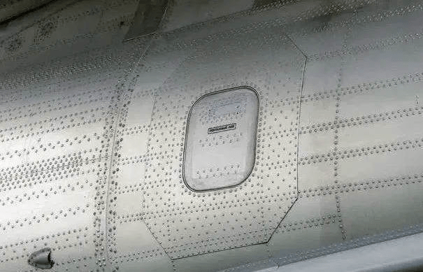
Engineers utilize the lightest materials feasible in aircraft building to reduce aircraft weight. Aircraft envelopes are often comprised of very thin materials. Welding together envelopes that are too thin is quite challenging. Furthermore, the composite material of the envelope is more vulnerable to welding damage, and the connectivity of different elements must be fixed physically. As a result, rivets are preferable.
2. The material to be welded will generate a lot of heat during flight and welding, and it is not suitable for use in aircraft.
A lot of heat is generated on the surface of an airplane when it is flying at high speeds. Because the temperature of the flying environment varies so much, this phenomena of thermal expansion and contraction will have a significant impact on the integrity of solder junctions.
Some airplane fuselages are built of aluminum, which has a low heat resistance. Because the welding procedure generates a lot of heat during the welding process, it is not suited for aircraft with aluminum fuselages.
3. The airplane has been in a resonance environment for an extended period of time.
Because the aircraft is in a resonance environment for an extended period of time when flying. It is easy to break if welding is applied.
4. Rivets are stronger than welding.
(1) Welding has numerous downsides. Welding, whether thin or thick, may have an effect on the aircraft.
(2) Rivets make the airplane safer, and they also help to reduce resistance in flight.
v(3) Using rivets can significantly cut costs.
(4) Rivets are less harmful to the environment than welding.
(5) If the turbulence is severe throughout the flight, the aircraft’s wings will swing up and down dramatically. The envelope of the wing is expanded or squeezed throughout the swing. If the welding procedure is employed, the weld’s strength will be greatly diminished when subjected to frequent stress variations. These welding spots are likely to develop some minor cracks over time. The weld is prone to metal fatigue after a long period of time.
The rivet connection can decrease the transmission of vibration between the joints, lowering the danger of shock cracking. The firmness is better and more reliable for such repetitive stress variations.
5. Riveting allows for standardized and quantitative output.
The welding quality is mostly determined by the operator’s expertise, and the randomness of the welding thickness is very high. It is still challenging to create consistent standards.
The characteristics of the rivets used in the riveting process have relatively tiny mistakes, making quality control and uniform production simple. Rivet machining accuracy is controlled to the micron level.
6.Rivets will lower the aircraft’s aerodynamic drag during flight.
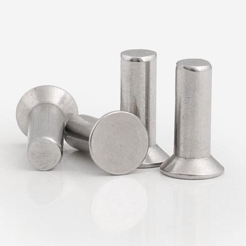
Rivets reduce rather than increase aerodynamic drag. Because the rivets used in the aerospace industry are mostly convex and countersunk. Because there is no demand for aerodynamic design in the interior of the aircraft, convex head rivets with low cost and easy processing are primarily used. Countersunk rivets are mostly employed on the aircraft’s exterior, where they can significantly reduce drag. During the milling process, there are rigorous tolerances for the nail cap and adjacent structures.
This application has produced outstanding outcomes. According to pertinent World War II data, the use of countersunk rivets can reduce aircraft resistance by around 3%.
Because of the unique characteristics of the oil drilling industry, the need for a drilling simulator is to save a significant amount of people and resources for drilling training. A petroleum drilling simulator is a type of virtual training equipment that simulates the driller’s work in a drilling operation by utilizing modern electronic technology and communication principles.
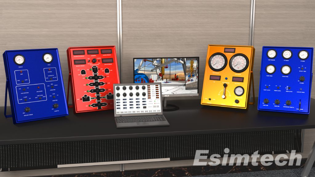
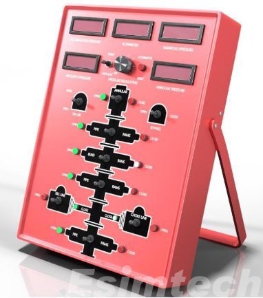
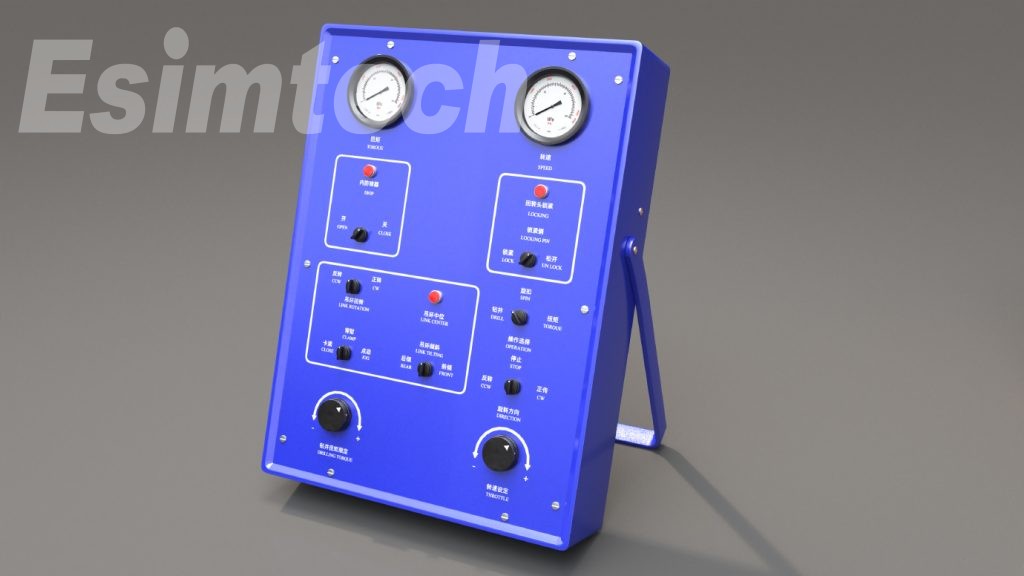
Esmitech has created a portable drilling simulator that sends operational instructions to the simulation console in order to obtain interactive control of the virtual 3D well pad.
The trainees can operate directly through the driller’s console simulator to restore the well site operation process, as if sitting in the driller’s control room, with a strong sense of presence and realism, thanks to the combination of simulator and 3D technology.
The Esmitech drilling simulator is portable, easy to transport, and can be used for mobile education. The simulator can create a network-based multi-user shared virtual environment in which users of various types of work training can control their own virtual characters and interact with the virtual characters controlled by others to achieve the goal of simulation training.
Features Of Esmitech Portable Driller Simulator
Control of physical operations
There is no sequenced driller operation mode.
True 3D picture interaction in real time
Sound effect of a realistic environment
Voice prompting in real time
Advanced and precise physical and mathematical models, in accordance with real-world process requirements
Cooperative operation in various sorts of work teams
The training material is methodical and comprehensive, and the project structure is adaptable.
User-friendly UI that is simple to learn
Functions Of Esmitech Portable Driller Simulator
Drilling modes, such as rotary table drilling simulator and top drive simulator, can be selected.
The parameters for beginning the drill can be changed to influence the drill’s operation dynamics.
Capable of displaying the well-site image.
Conduct training on a variety of drilling operations, such as tripping out and joining single pipes.
Drilling simulation should be done interactively. The system receives the operation command from the operation console, evaluates its action attribute, and provides feedback.
The training program essentially covers all drilling procedures, including rotary table drilling and top drive drilling. Patrol inspection, drilling operation, and accident handling are all part of the rotary table and top drive drilling operation modules, respectively.
(1) Rotating drilling operation patrol inspection
The drilling project
1. drilling and joining a single pipe
2. stumbling and falling in the hole
3. casing operation
(2) The accident handling operation can be carried out by the teacher randomly introducing equipment and downhole defects during the well control simulator operation, so that the trainees can learn the judgment and fault handling procedures.
Applications Of Esmitech Portable Drilling Simulator
It can handle downhole accidents like stuck tripping, stuck tripping, high-pressure formation drilling, low-pressure formation drilling, adhesive sticking, sand setting sticking, mud bag sticking, drill pipe suction, well kick caused by high-pressure permeability layer, multiple well kick, lost circulation, underground blowout, out-of-control blowout, out-of-control blowout, and fire.
The Esmitech Portable Drilling Simulator is a versatile tool that can be utilized in a variety of drilling-related tasks. The simulator is commonly used for the following purposes:
Training: The simulator is a fantastic training tool for all levels of drilling operators. It provides a safe and regulated environment for practicing skills and techniques such as drilling, tripping, and well management.
Assessment: The simulator can be used to evaluate drilling operators’ abilities and competency. It gives instructors real-time feedback on their students’ performance, allowing them to discover areas for development and provide specific comments and coaching.
Research and development: The simulator can be used for drilling-related research and development. It can be used to evaluate the effectiveness of different drilling procedures, as well as detect potential risks and hazards related with drilling operations.
Training for emergency response: The simulator can be used to mimic emergency events such as well blowouts or equipment breakdowns. Drilling operators can practice emergency response methods in a safe and controlled environment.
Reasons Why Buy Drilling Simulator From Esmitech
Pre-job planning: Before implementing drilling plans and procedures in the field, the simulator can be used to develop and test them. This can assist in identifying potential problems or concerns and refining the plan prior to the start of real drilling operations.
The Esmitech portable drilling simulator is a highly advanced and realistic simulator built for drilling operator training and improvement. It has a number of features and benefits that make it an appealing option for individuals looking to improve their drilling skills. Among these traits and benefits are:Portability: The Esmitech Portable Drilling Simulator is small and portable, making it perfect for usage in distant areas or where room is limited.
Realistic simulation: The simulator simulates several drilling scenarios and conditions to deliver a highly realistic drilling experience. This enables workers to hone their abilities in a safe and regulated environment without risk of damaging equipment or causing mishaps.
Customizable scenarios: The simulator enables for the construction of customizable scenarios that can be tailored to the operator’s or organization’s individual needs and training goals.
Cost-effective: The simulator is a less expensive alternative to typical training methods including on-the-job training or costly drilling courses.
Continuous improvement: Because the simulator gives quick feedback on performance, operators can discover areas for improvement and fine-tune their skills.
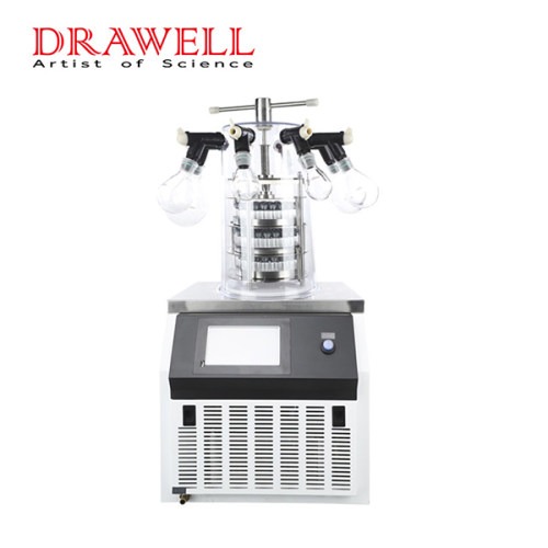
A freeze dryer is a scientific method that pre-freezes water-containing goods before sublimating their moisture in a vacuum state to produce dry items. The freeze-dried items can be preserved for an extended period of time and can be restored to their pre-freeze-drying state while retaining the original biochemical properties after adding water.
Vacuum freeze-drying technique has numerous applications in bioengineering, pharmaceutical industry, food industry, material science, and deep processing of agricultural and byproduct products, and the scale and field are continually developing. To that purpose, vacuum freeze-drying will be a significant application technology in the twenty-first century.
The refrigeration system, also known as the “heart of the freeze dryer,” is the most critical component of the freeze dryer. Compressor, refrigerant, oil separator, water condenser, filter drier, intercooler, sight glass, solenoid valve, hand valve (top cover valve), expansion valve, evaporation (plate exchanger, rear box condensing coil), vapor-liquid separator, return air filter, pressure gauge, pressure control relay, CPCE (energy regulator), safety valve, refrigeration pipeline, and other components comprise its refrigeration system.
How does Freeze Dryer work?
Freeze drying is a drying process that works on the sublimation concept. It is a method that involves rapidly freezing dry material at a low temperature and then directly sublimating the frozen water molecules into water vapor in a suitable vacuum environment. Freezing The dried product is known as a lyophilizer, and the process is known as lyophilization.
After the liquid refrigerant absorbs the heat of the cooled material in the evaporator, it is vaporized into low-pressure and low-temperature steam, which is inhaled by the compressor, compressed into high-temperature and high-pressure steam, and then discharged into the condenser. It releases heat to the cooling medium (water or air), condenses into a high-pressure liquid, is throttled by a throttling device to a low-pressure and low-temperature liquid, and enters the evaporator again to absorb heat and vaporize.
How do I select a freeze dryer?
Many precise features must be considered while selecting a freeze drier. Customers must purchase a freeze dryer that meets their requirements. When selecting a freeze dryer, examine not only the price, but also the temperature of the cold trap, the cooling rate, the temperature homogeneity of the board, the flatness, and other indicators.
Cold Trap Temperature
A cold trap is a device that traps water during the freeze-drying process. In theory, the lower the temperature of the cold trap, the greater its ability to catch water. The experimental series freeze dryer’s cold trap temperature has multiple classes, including -45°C, -60°C, and -80°C. Some items that are easily freeze-dried can benefit from freeze-drying with a cold trap temperature of -45°C. Most items can be freeze-dried using freeze-drying devices with a cold trap temperature of around -60°C. Freeze-drying with a -80°C cold trap temperature It is appropriate for the lyophilization of some specialty items. The influence of cold trap temperature on water-capturing ability was experimentally established, with the water-capturing capacity greatly increased when the temperature of the cold trap dropped from -35°C to -55°C. In the absence of unique requirements, a cold trap temperature of roughly -60 °C is an excellent choice.
Cooling Rate
The cooling rate reflects the refrigeration system’s cooling capacity. The temperature of the cold trap shall reach the minimum temperature indicated in the index within 1 hour under no-load conditions. For a freeze dryer with a cold trap temperature of -60 °C, for example, the machine begins timing from the time the machine is turned on for refrigeration, and the time for the cold trap temperature to reach -60 °C should not exceed 1 hour.
Ultimate Vacuum
The final vacuum degree shows the leaking of the freeze drier as well as the vacuum pump’s pumping performance. The freeze-drying box’s vacuum level. Previously, the higher the vacuum degree, the better. According to contemporary thinking, the vacuum degree should be within a tolerable range. The vacuum degree is too high, which inhibits heat transfer and slows drying, yet the no-load limit vacuum degree of the freeze-drying box should be greater than 15Pa.
Uniformity of plate temperature and flatness
The consistency and flatness of plate temperature have a significant impact on product quality uniformity. The higher the temperature uniformity and flatness, the higher the quality of the freeze-dried product. The temperature of the freeze dryer shelf can be controlled by a heater or an intermediate fluid. The temperature uniformity and flatness of the freeze dryer shelf with an intermediate fluid control layer are excellent. This layer of freeze dryer plate is a hollow sandwich structure. The cooling and heating of the plate are accomplished through the circulation of the intermediate fluid in the fluid channel within the plate, resulting in consistent plate temperature. The fluid in the centre of the shelf technology is used by the freeze dryer. The bell-type freeze dryer’s shelf temperature control employs a heater, resulting in slightly poorer temperature uniformity of the plating layer. However, the temperature difference between the layers of the medical freeze dryer should be kept within 1.5 °C, and the temperature difference inside the plate should be kept within 1 °C, and the food freeze dryer can be suitably relaxed.
Summary
We can deduce from the preceding information that different types of laboratory freeze dryers should be used depending on the industry. For many years, DRAWELL has been the most successful freeze dryer producer in China, offering high-quality freeze dryers to laboratories all over the world. Please contact us if your laboratory requires a freeze dryer or other laboratory equipment; we will be your best choice.
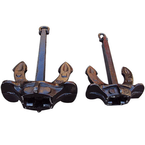
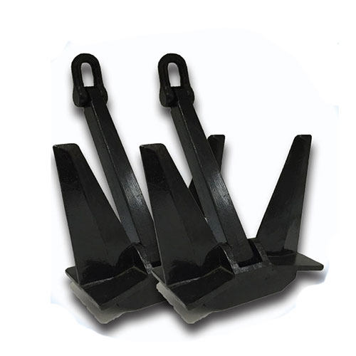
Marine anchors are essential components for keeping marine vessels moored securely. These devices are designed to give the vessel a secure and steady hold on the bottom, preventing it from drifting away due to wind, current, and wave forces.
Principle Of Marine Anchor
The principal purpose of a marine anchor is to create a holding force that keeps a vessel in place while at anchor or moored. The anchor is designed to sink into the seafloor and endure wind, tide, and wave stresses that would otherwise cause the vessel to drift or be damaged. When the anchor is fully set and the chain or rope is taut, it provides a holding force that is transmitted to the vessel.
An anchor’s ability to generate a holding force is governed by its design and the resistance it encounters as it sinks into the bottom. The anchor must be heavy enough to sink into the seafloor and withstand the vessel’s forces. It must also be able to penetrate the seafloor and take a strong grip.
The chain or rope that connects the anchor to the vessel must be strong enough to withstand the tension and stress induced by wind, current, and waves, as well as the weight of the vessel. The length of the chain or rope is also important since it determines the angle of the anchor as well as the amount of holding force supplied to the vessel.
Explanation of the role of the anchor and chain in establishing a secure hold
The anchor and chain or rope are crucial in generating a stable hold for a moored or at anchor vessel.
For starters, the anchor is the vessel’s primary point of contact with the seafloor. Its purpose is to sink into the seafloor and generate a holding force that can endure the forces of wind, current, and waves. Once the anchor is properly embedded in the seafloor, it offers a strong foundation for the vessel’s stability.
Second, the chain or rope connects the anchor to the vessel and transfers the anchor’s holding force to the vessel. The chain or rope must be strong enough to withstand the tension and stress created by wind, current, and waves, as well as the weight of the vessel. The length of the chain or rope is also important since it determines the angle of the anchor as well as the amount of holding force supplied to the vessel.
A major component that permits a vessel to remain at anchor or moored is the anchor and the chain or rope. Without the anchor, the vessel would be subject to the forces of wind, current, and waves and may be washed away or damaged. Similarly, without a strong and dependable chain or rope, the anchor cannot convey holding power to the vessel, and the vessel cannot remain in place.
What are the Factors that Affect the Sinking Depth and Resistance
The greater the gripping force, the deeper the anchor dives and the greater the resistance. The ideal mix of anchor weight, design, chain/rope length, and anchor type is decided by the operating conditions as well as the vessel’s size and weight.
Anchor weight
A heavier anchor sinks further and provides more resistance than a lighter anchor.
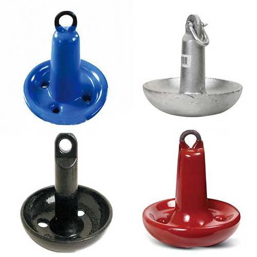
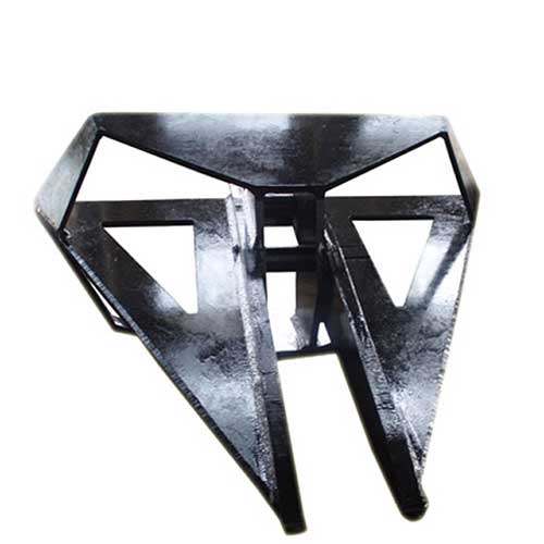
Anchor design
The shape and design of the anchor determine its ability to penetrate and retain in the seafloor. Different designs are better suited to different types of seafloor.
Seabed composition
The composition of the seabed effects the anchor’s capacity to penetrate and hold. Soft, muddy seafloors are less resistant to erosion than hard, stony seafloors.
Anchor chain/rope length
The length of the anchor chain or rope determines both the angle at which the anchor sets and the amount of holding force it may generate. The anchor can be positioned at a flatter angle with a longer chain or rope, providing extra holding force.
Water depth
The depth of the water influences the length of the chain or rope required, as well as the amount of resistance that the anchor must provide.
Current and wind speed
The speed and direction of the current and wind influence the stress on the anchor and the amount of resistance it must provide to keep the vessel in place.
Vessel size
The amount of resistance required to keep the vessel in place is affected by its size and weight.
Anchor type
Different types of anchors operate differently in different settings. Some anchors are more effective on sandy or muddy seabeds, whereas others are more effective on rocky seabeds.
How the Holding Force Affected by the Marine Anchor
The holding force created by a marine anchor is a function of its design and the resistance it encounters as it sinks into the seabed. Once the anchor is fully set and the chain or rope is taut, the anchor generates a holding force that is transmitted to the vessel.
1. The surface area of the anchor that makes contact with the seafloor influences the holding force it produces. Anchors with bigger surface areas generate more holding force than smaller surface area anchors.
2. The design of the anchor determines its ability to penetrate the seafloor and generate holding force. Some anchor designs are better suited to soft or muddy seabeds, while others are better suited to rocky seabeds. The angle at which the flukes or blades of the anchor are positioned, as well as their shape, impact the anchor’s ability to penetrate and hold.
3. The anchor’s holding force is affected by the depth to which it sinks and the resistance it encounters as it sinks into the seafloor. A heavier anchor will generate more holding force than a lighter anchor that dives shallower and encounters less resistance.
4. The length and strength of the chain or rope that connects the anchor to the vessel influence the holding force delivered to the vessel. A longer, stronger chain or rope allows the anchor to be set at a flatter angle, resulting in greater holding force.
Summary
The article describes how marine anchors work, how they are used to secure boats, ships, and other marine vessels, and how the process of sinking the anchor into the seabed and creating the holding force that keeps the vessel in place works.
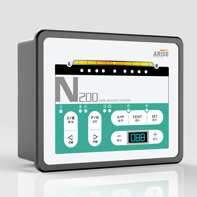
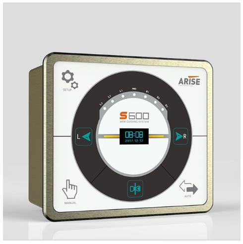
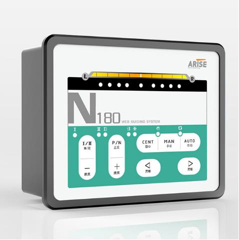
In a web guiding system, PID control enhances precision, decreases variability, has a faster response time, and is adaptable to different web materials. We will introduce a web guide PID controller and explore its description, operating principle, benefits, applications, and difficults associated with its use in this part.
What is a Web Guide PID Controller
A web guide PID (Proportional-Integral-Derivative) controller is a closed-loop control system that uses sensor feedback to automatically change the location of a moving web material, such as paper, plastic, or fabric, to maintain it aligned with a desired route or edge. The web guide controller constantly monitors the position of the web material and calculates an error signal based on the difference between the desired and actual positions.
The PID controller then changes the output of an actuator, such as a motor or pneumatic cylinder, to correct the position of the web material. To change the output signal depending on the error signal, the rate of change of the error signal, and the integral of the error signal over time, the PID controller employs three control components.
How does a Web Guide PID Controller Work
The operating principle The web guide PID controller is concerned with maintaining the alignment of a moving web material.
The PID controller continuously monitors the position of the web material using one or more sensors. These sensors could be edge guide sensors, line sensors, or other sorts of sensors, depending on the application. Based on the difference between the actual position of the web material and a desired path or edge, the controller determines an error signal.
The PID controller then changes the output of an actuator, such as a motor or pneumatic cylinder, to correct the position of the web material. The actuator could be linked to a guiding roller, a steering roller, or another web handling system component, depending on the specific design.
The Proportional, Integral, and Derivative components of the PID controller are employed in that sequence to change the output signal based on the error signal, the rate of change of the error signal, and the integral of the error signal over time. This enables the controller to make precise and exact adjustments to the position of the web material.
In a web guiding system, the proportional component of the PID controller is typically used to respond quickly to changes in the position of the web material, while the integral component is used to eliminate steady-state errors and the derivative component is used to reduce overshoot and dampen the response to disturbances.
The tuning parameters of the PID controller can be modified to optimize its performance for different web materials, speeds, and other operating scenarios. Depending on the complexity of the web handling system, the web guide PID controller can be configured to operate in single-axis, dual-axis, or multi-axis control modes.
What are the Benefits of a Web Guide PID Controller
Improving accuracy and precision
The PID controller may precisely adjust the placement of the web material, improving the web handling system’s accuracy and precision.
Reducing waste
By assuring proper alignment of the web material, the web guide controller helps prevent waste caused by misalignment, wrinkling, or other material faults.
Increasing productivity
The controller can keep the web material aligned at high speeds, boosting the efficiency of the web handling system.
Flexibility
Depending on the complexity of the web handling system, the PID controller can be configured to operate in single-axis, dual-axis, or multi-axis control modes. As a result, it is an adaptable solution for a wide range of web-handling applications.
Adaptability
The web guide controller can adapt to changes in the web handling system, such as differences in web speed, tension, or material characteristics, to ensure precise alignment of the web material.
Reduced operator intervention
The web guide PID controller may run autonomously, reducing the need for user participation and increasing system reliability.
What are the Applications of a Web Guide PID Controller
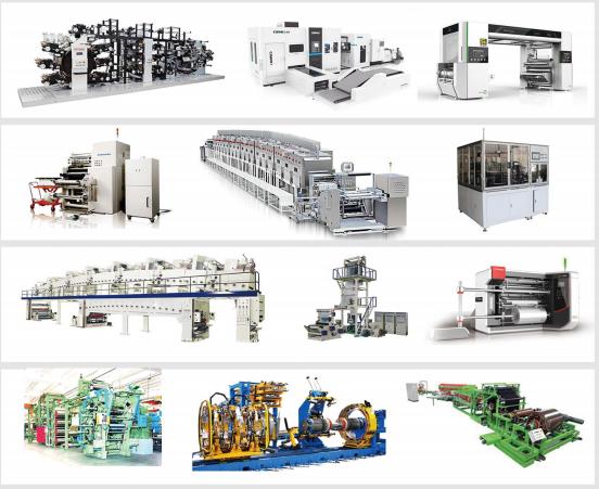
PID controllers for web guides are utilized in a variety of manufacturing and processing applications where precise control of web materials is required.
Printing
Web guides are used in printing applications. PID controllers are utilized to keep the web material aligned accurately during printing, decreasing waste and enhancing print quality.
Converting
Creating a Web Guide PID controllers are used in converting applications such as cutting or slitting of materials to ensure accurate web material alignment, reduce waste, and improve the quality of the converted output.
Packaging
Web guidelines for packaging are utilized in packaging applications. PID controllers are used to keep web material alignment correct during packaging operations, reducing waste and improving packaged product quality.
Coating
Web guide PID controllers are used in coating applications such as coating films or papers to keep the web material aligned, hence improving the quality of the coated result.
Textile
Web guide PID controllers are used in textile applications to maintain perfect fabric alignment during weaving or knitting operations, hence reducing wastage and improving quality.
Automotive
Web guide PID controllers are used in automotive manufacturing applications to keep materials perfectly aligned throughout processes such as cutting, stamping, or laminating, hence improving the quality of the manufactured automobile components.
What are in Difficults For a Web Guide PID Controller
Non-linear behavior of web materials
Web materials can exhibit non-linear behavior, making it challenging to forecast and control their position. This could induce oscillations or overrun in the control system.
Varying material properties
Thickness, elasticity, and surface characteristics of web materials may influence the behavior of the web handling system. This can make tweaking the PID controller for peak performance difficult.
External disturbances
External disturbances, such as changes in web tension or air drafts, may affect the position of the web material, resulting in mistakes in the control system.
Sensor positioning and precision
The accuracy and location of web guide sensors used to measure the position of the web material can have an effect on the operation of the control system. Inaccurate sensor readings can lead to incorrect control actions.
Maintenance and calibration
The PID controller and its supporting hardware components must be repaired and calibrated on a regular basis to ensure optimal operation. This may need downtime for the web handling system, affecting production timetables.
The technical level of operators directly influences the efficiency of oil and gas operations. Esmitech has released a range of oil simulators to help operators increase efficiency by simulating scenarios. Esmitech is dedicated to increasing the safety and efficiency of the petroleum sector as the world’s top provider of drilling simulation technology.
The Esmitech simulator complies entirely with IADC and IWCF requirements, delivering the most stringent industry standards for drilling and well control simulation training. The Esmitech simulator portfolio comprises portable and full-size drilling and well control simulators, as well as complex network base models for specific customer needs.
What is Portable Drilling Simulator?
The portable drilling simulator is extremely practical and can play a huge role in different kinds of operations. Compared with other technologies, its characteristics are very obvious. Using portable drilling simulator, drilling, well control training can be conducted on a single simulator platform, and can be packaged in a customized protective sleeve for transportation.
The module-based learning management system has a user-friendly interface that is easy to operate and use. Esmitech simulator supports human-machine interface system and drilling simulator of various oil drilling rigs to track and report the progress and development of training and simulation operations in a timely manner.
For the performance in training, the evaluation, feedback and improvement functions in simulation can play a significant role in improving. In addition, cloud-based dashboards can be used to remotely monitor the ability of operators. In addition, cloud-based dashboards can be used to remotely monitor the ability of operators.
Advantages of Using Portable Drilling Simulator
Portable drilling simulators can help improve safety by providing workers with a realistic training experience in a controlled setting, allowing personnel to practice procedures and methods without the risk of real-world mishaps.
Savings on equipment and staff: Portable drilling simulators can be a cost-effective alternative to traditional field training, which can be costly due to the need for specialized equipment and personnel.
Portable drilling simulators can provide workers with a realistic and engaging learning experience, helping to enhance learning outcomes and retention rates.
Portable drilling simulators can be used to standardize training across different locations and teams, ensuring that everyone is trained to the same level and using the same methodology.
Portable drilling simulators can help boost productivity by minimizing the time necessary for on-the-job training and allowing workers to become adept in their abilities more rapidly by allowing workers to practice processes and techniques in a virtual environment.
Portable drilling simulators can be an effective tool for enhancing drilling and well control safety by providing workers with a realistic and engaging training experience that eliminates the need for expensive and time-consuming field training.
How Portable Drilling Simulator Used For Improving Operation Efficiency In Petroleum Industry
Portable drilling simulators can help the petroleum sector enhance operational efficiency in a variety of ways. Some examples are:
Portable drilling simulators can provide workers with a realistic and engaging training experience, which can aid in improving learning outcomes and retention rates. This can help people become more skilled in their abilities faster and reduce the amount of time necessary for on-the-job training.
Portable drilling simulators can be used to standardize training across different locations and teams, ensuring that everyone is trained to the same level and using the same methodology. This can help increase operational consistency and reduce the likelihood of errors and mishaps.
New technology testing and evaluation: Portable drilling simulators can be used to test and assess new technologies such as automation systems and remote monitoring tools. This can help companies identify ways to improve efficiency and reduce costs in drilling and well control operations.
Virtual drills and simulations can be conducted using portable drilling simulators, allowing workers to practice emergency response protocols in a safe and controlled setting. In the event of an actual disaster, this can help increase readiness and reaction times.
Portable drilling simulators can be used to test worker performance and indicate areas where more training may be required. This can assist businesses in identifying areas for improvement and ensuring that employees are functioning at their best.
Companies in the petroleum industry can increase operation efficiency and decrease the risk of accidents and downtime by employing portable drilling simulators to improve training, evaluate new technologies, and analyze worker performance.
ESIM-PDS9B Portable Drilling Simulator
The real-time portable drilling simulator trains drill rigs on drilling operations, equipment control, well control, and crane operation. The interactive device’s non-teacher mode and the long-term provision of training, development, and evaluation are fundamentally redefining the drilling industry’s training mode. The operators can create and perform drilling and well control exercises, as well as display downhole conditions in 3D images. This allows learners to see and understand the repercussions of their actions, as well as the ramifications of the same actions in different drilling operations.
Advantages
Economy: by allowing unlimited team practice, you may maximize your return on investment.
Ensure that the team is well-trained and capable and that it adheres to internationally accepted standards.
Reality: providing hands-on training without endangering assets, workers, or the environment.
Interactivity: make team training easier and more interactive through four consoles.
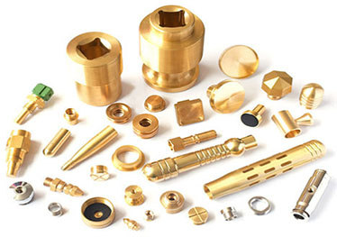
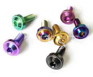
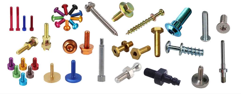
Screws are brightly colored. Screw fasteners of various colors, such as silver, black, yellow, purple, and so on, can be found everywhere. So, how did these multicolored screws come to be? Screw plating is a procedure that adds vibrant colors and beauty to screw fasteners.
Screw plating is used for colored products
The screw is quite greasy and unclean when it is freshly manufactured. At this moment, it must be brought to an electroplating plant to be made attractive and functional. The color of the screw electroplating can be matched with the color of the material. When a screw fastener is plated, it takes on a more colorful and bright appearance.
Screw plating is available in white zinc, blue zinc, colorful zinc, white nickel, black nickel, black zinc, and green.
What should be paid attention to during the screw plating process?
1. If screws with different specifications mix together for electroplating, some areas cannot be plated, resulting in product scrapping. Before electroplating, the screws must be cleaned.
2. It is difficult to achieve the quality requirements of electroplating layers and diverse specifications, such as the appearance color and screw properties, under the process conditions of conventional electroplating, most of which require professional operation.
3. Screw specs are too near, for example, the size and length appear to be the same. This type of screw plating should be done separately; otherwise, it is difficult to screen.
4. Plate heavier screws and lighter screws separately. To electroplate, smaller and larger screws should be separated. Otherwise, screws of various specifications and models become locked together during the electroplating process, causing harm to the screw.
5. The screws are easily electrocuted when they become trapped together. Otherwise, the two distinct specifications and models of screws become entangled, which quickly leads to plating failure, even after the screw plating has been completed. It is also difficult to separate different types of screws.
Quality control methods of screw plating product
The key measurement standard for screw plating quality is corrosion resistance and attractiveness. The corrosion resistance is designed to mimic the product’s environment. Set the test settings to the environment and conduct the corrosion test. So, what are the quality assurance procedures for screw electroplating products?
1. Appearance
The screw’s entire surface must be coated. Scorching, roughness, grayness, peeling, crusting, visible stripes, pinholes, loose passivation film, cracking, and severe passivation traces are not permitted.
2. The thickness of the plating
In a corrosive environment, the service life of a self-tapping screw is directly proportional to the plating thickness. Hot-dip galvanized has an average thickness of 54um and a minimum thickness of 43um.
3. Distribution of plating
The plating aggregation technique on the fastener surface differs. The plating metal is not consistently deposited on the edge of the outer peripheral while plating. To achieve a thicker plating at the corner, various accumulation processes are used. The screw’s thickest plating is at the top of the thread, gradually becoming thinner at the front of the thread, and thinnest at the bottom. Hot dip galvanizing is the polar opposite. The inner corner and bottom of the thread receive thicker plating. Mechanical plating has the same metal accumulation propensity as hot dip plating, but it is considerably smoother and the thickness of the overall appearance is much more consistent.
4. Embrittlement due to hydrogen
When fasteners are processed, particularly during the pickling and alkaline processes before to plating and subsequent electroplating, the appearance absorbs the hydrogen atom, and the accumulated metal plating captures hydrogen. When the screw is tightened, the hydrogen moves to the most concentrated region of the stress, causing the pressure to rise to levels that exceed the strength of the base metal, resulting in a little appearance fracture. Hydrogen is especially aggressive and quickly enters into newly created cracks. This cycle will continue until the fastener snaps. It usually happens within a few hours of the first stress. To reduce the risk of hydrogen embrittlement, the fastener should be heated as soon as possible after plating to allow the hydrogen to be expelled from the plating. The heat treatment is normally performed for 3-24 hours. Mechanical galvanizing is non-electrolyte, hence the threat of hydrogen is eliminated.
Summary
Screw plating gives fastener products vivid colors, making them beautiful, colorful, and gorgeous. What should be paid attention to throughout the electroplating process and how to control the quality of the screw products are major concerns. The article provides some important information for improving the effect of screw plating.