Well intervention is an important aspect of the oil and gas industry and encompasses a wide range of techniques and technologies to optimize oil and gas well performance. From routine maintenance to major repairs and upgrades, well intervention plays a critical role in maximizing the production and profitability of oil and gas assets while ensuring safety and environmental sustainability.
However, well intervention is also a complex and constantly evolving field influenced by a variety of factors, including geology, reservoir characteristics, drilling and completion technologies, and regulatory requirements. Therefore, a multidisciplinary approach is required that combines technical, scientific, and operational expertise, as well as collaboration and communication among the various stakeholders.
In this article, we address the fundamentals of well intervention in the oil and gas industry and examine the various methods and tools used to diagnose, analyze, and resolve downhole issues. We also discuss the challenges and opportunities facing the industry, as well as the latest trends and innovations that will shape the future of well intervention. Whether you are a seasoned professional or a curious newcomer to the industry, we hope this article will provide you with valuable insight and inspiration for your work.
What is well intervention in the oil and gas industry?
Well intervention is a critical process in the oil and gas industry that involves various activities aimed at maintaining, improving and restoring oil and gas well productivity. This article provides an overview of well intervention, the different types of well intervention techniques, and their importance to the industry.
Well intervention can be divided into two broad categories:
Light interventions: These are generally less complex and low-cost techniques, such as slickline, coiled tubing, and wireline interventions. These methods use specialized tools and equipment to perform various tasks downhole.
Heavy intervention: these are typically more complex and expensive techniques, such as hydraulic workover rigs and snubbing units. These methods use heavy equipment to perform more extensive downhole operations, such as drilling or recompleting a wellbore.
Overview of downhole intervention techniques
There are several types of well intervention techniques that can be broadly categorized into two main groups: Workover and Stimulation. Workover refers to activities that restore the productivity of previously drilled wells, while stimulation refers to activities that increase the productivity of new and existing wells.
Common well intervention techniques include:
Slickline: This involves inserting a thin, flexible wire into the wellbore to perform various tasks such as setting or pulling out valves, gages, and plugs.
Coiled tubing: this involves inserting a long, continuous metal tube into the wellbore to perform various tasks such as cleaning, acidizing, and fracturing.
Wireline: This uses an electrical cable to perform various tasks such as logging, perforating, and sampling.
Hydraulic workover: Here, a hydraulic workover rig is used to perform various tasks such as drilling, completions, and workover operations.
Cut-off: This involves using a snubbing unit to perform various tasks, such as drilling, completions, or workover operations, under pressure.
The most common workover techniques include snubbing, coiled tubing and wireline. Stimulation techniques, on the other hand, include hydraulic fracturing, acid stimulation and sand control. Each of these techniques has its own advantages and disadvantages, and the choice of technique depends on the specific well conditions and desired outcome.

What equipment is used in borehole intervention?
Various equipment and tools are used in well intervention, depending on the particular technique and conditions of the well. Commonly used equipment in borehole intervention include:
Coiled tubing: a long, flexible metal tube used to pump fluids and chemicals into the wellbore or to retrieve wellbore debris.
Flushing unit: A hydraulic system that applies pressure to the coiled tubing to perform workovers, such as replacing damaged equipment or plugging wells.
Wireline tools: a set of tools that are lowered into the wellbore on a wireline to perform operations such as logging, perforating, and plug setting.
Hydraulic fracturing equipment: a set of pumps and tanks used to inject fluids and proppants into the formation to create fractures and stimulate oil and gas flow.
Sand control equipment: a set of screens and filters that prevent sand and other contaminants from entering the well and clogging production equipment.
Pressure control equipment: a series of valves, blowout preventers, and other devices used to regulate downhole pressure and fluid flow.
Wellhead equipment: a set of valves and fittings used to control the flow of fluid into and out of the wellbore.
Downhole tools: a set of tools lowered into the wellbore on a wireline or coil to perform operations such as perforating, logging, and cleaning.
The choice of equipment depends on the specific intervention technique and the conditions of the borehole. Downhole interventions are typically performed by a team of experienced personnel trained to use the equipment safely and effectively.

What are the methods of well activation?
Well activation is the process of starting or resuming production in a shut-in or temporarily abandoned well. There are several methods of well activation, depending on the particular situation and conditions of the well.
Common methods of well activation include:
Mechanical stimulation: mechanical stimulation uses tools such as downhole pumps, gas lift systems, and jet pumps to increase the flow of fluid from the wellbore. This technique is often used on wells that have low or declining flow rates due to blockages or damage in the wellbore.
Acid stimulation: acid stimulation involves injecting acid into the formation to dissolve or remove blockages and improve the permeability of the rock. This technique is commonly used in carbonate formations and can improve well productivity by increasing fluid flow into the well.
Hydraulic fracturing: hydraulic fracturing involves injecting fluids and proppants into the formation at high pressure to create fractures and stimulate oil and gas flow. This technique is commonly used in shale formations and can significantly increase well productivity.
Waterflooding: waterflooding involves injecting water into the formation to force oil to the production well. This technique is often used in mature oil fields and can increase production rates by improving reservoir efficiency.
Gas injection: gas, such as nitrogen or natural gas, is injected into the formation to reduce the viscosity of the oil and increase fluid flow. This technique is often used in wells with heavy oil or in reservoirs that are difficult to produce.
The choice of well activation method depends on the situation and the characteristics of the well and reservoir. Well activation is usually performed by a team of experienced personnel who are trained to use the equipment and techniques safely and effectively.
Why is well activation so important?
Well activation is critical to the oil and gas industry because it helps maintain the productivity of oil and gas wells, which are the main source of revenue for oil and gas companies. Neglecting wells can lead to a decline in production rates, which can ultimately result in financial losses for the company. Early intervention is therefore critical to ensure that wells are productive and profitable.
The benefits of early intervention include higher production rates, improved safety, and lower costs associated with deferred maintenance. Neglecting wells, on the other hand, can lead to an increased risk of equipment failure, which can be a safety hazard and result in costly repairs.
Cost-benefit analysis of well intervention
Well intervention is a costly process, and the costs associated with each technique depend on several factors such as the type of well, the depth of the well, and the technique used. The cost of well intervention can be significant, but it is important to consider the potential benefits in terms of increased production rates and revenue.
Factors influencing the decision to intervene in a well include the age of the well, the production history of the well, and the potential for increasing production rates. A cost-benefit analysis can help determine whether or not well intervention is a financially viable option.

Case studies of successful well intervention
There are numerous examples of successful well interventions in the oil and gas industry. For example, a well intervention project in the North Sea helped increase production rates by 300%, while a project in the Gulf of Mexico resulted in a 20% increase in production rates.
The success of these projects can be attributed to the use of effective techniques and strategies, such as the use of innovative technologies, optimization of production processes and the deployment of experienced personnel.
Conclusion
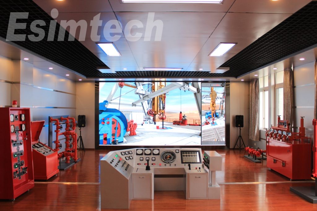
Well rehabilitation is an important process in the oil and gas industry that helps to maintain well productivity and ensure the profitability of oil and gas companies. The choice of technology depends on several factors, including specific well conditions and the desired outcome. Emerging technologies such as robotics and artificial intelligence have the potential to improve the efficiency and effectiveness of well intervention techniques in the future. If you are looking for a professional well intervention training system, Esimtech can help!