Well Control Simulators: Enhancing Safety and Efficiency of Drilling Operations in the Oil and Gas Industry

Maintaining well control, which involves regulating pressure and fluids in the wellbore, is a critical aspect of drilling operations to prevent unintentional hydrocarbon release. Well control simulators have emerged as invaluable training tools to enhance the expertise and preparedness of drilling personnel.

drilling and well control simulation system

What Are Well Control Simulators?

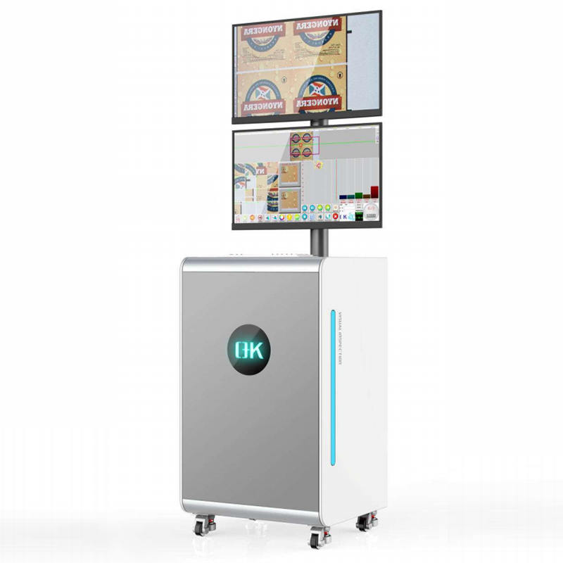
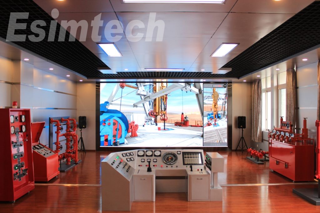
Well control simulators are advanced training tools that replicate the real-world well control environment within a controlled and safe setting. Leveraging cutting-edge technology, these simulators create a virtual well control experience, allowing trainees to practice well control procedures and techniques without any risk of real-world consequences. They provide a risk-free environment where drilling workers can refine their well control skills, improve decision-making abilities, and gain hands-on experience.

Advantages Of Well Control Simulators

Realistic Scenarios: Well control simulators excel in reproducing real-world well control scenarios. They can simulate various well control circumstances, including different types of kicks, blowouts, and pressure-related incidents. By simulating diverse well types, geology, and drilling equipment, trainees gain confidence and proficiency in dealing with well control challenges they may encounter in the field.

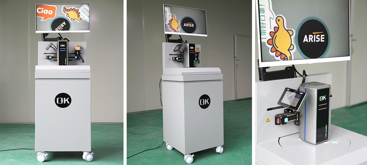
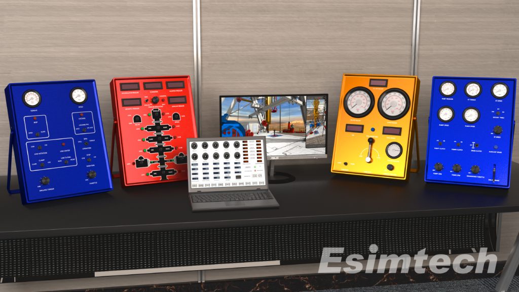
Hands-On Training: Portable well control simulators offer trainees the opportunity to familiarize themselves with the functioning of well control equipment and systems. They can practice operating various types of equipment, such as blowout preventers (BOPs), choke and kill manifolds, and pressure control systems, to improve competency. This hands-on training aids in developing muscle memory and reflexes, critical in high-pressure well control scenarios.

Dynamic and Realistic Environment: Well control simulators provide a dynamic training environment equipped with sophisticated monitoring systems that continuously measure wellbore pressure, temperature, and other parameters. Trainees can react to changing wellbore conditions and make necessary adjustments to maintain well control. This fosters quick thinking, decision-making, and problem-solving abilities, all vital in well control operations.

Immediate Feedback and Assessment: Well control simulators offer quick feedback and assessment. They continuously monitor trainee performance, providing feedback on various factors such as wellbore pressure and mud characteristics. This feedback loop enables learners to analyze their performance and adjust well control measures accordingly, enhancing their skills and knowledge.

Portable Drilling Well Control Simulation Training System

Customized Well Control Simulators From Esimtech

Esimtech, a leading provider of simulation systems for petroleum engineering and equipment, specializes in creating customized well control simulators tailored to the specific training needs of different drilling operations. These simulators can replicate the features of various wells, formations, and drilling equipment, offering a truly realistic training experience. They can also simulate different well control scenarios, such as shallow gas kicks, deep water well control, and high-pressure/high-temperature (HPHT) well control, allowing trainees to practice handling diverse well control situations they may face in the field.

Summary

Well control simulators, with their immediate feedback and customized training capabilities, are instrumental in improving the competency and preparedness of drilling personnel. By providing a risk-free environment for honing well control skills, well control simulators contribute to the safety and efficiency of drilling operations in the oil and gas industry.

Virtual Reality (VR) Technology: Revolutionizing Drilling and Well Control Training in the Oil and Gas Industry

The oil and gas industry is witnessing a significant transformation with the growing adoption of Virtual Reality (VR) technology, particularly in training and simulation applications. VR has emerged as a game-changer in drilling and well control training, offering trainees a safe, controlled, and immersive learning environment to develop their skills.

VR Emergency Training Simulator

Traditionally, drilling and well control training involved live sessions on actual oil rigs, which came with inherent risks, high costs, and time-consuming logistics. However, VR technology has revolutionized this training process by providing trainees with a realistic simulation of an oil rig, ensuring they can learn and practice without any real-life dangers.

One of the most significant advantages of VR technology is its ability to create 3D virtual environments that accurately replicate real-world oil rigs. The simulator can be programmed to emulate various drilling scenarios, enabling trainees to practice and refine their skills in a controlled setting. Moreover, it can recreate hazardous situations that are challenging or impossible to replicate in reality, allowing trainees to practice emergency procedures and responses without any actual risks.

The adoption of VR technology in drilling and well control training offers several benefits, including:

Improved Safety: Safety is paramount in the oil and gas industry, known for its hazardous work environments. Live training on real oil rigs exposes trainees to potential dangers, even with strict safety protocols. VR technology provides a safer alternative by enabling trainees to experience realistic scenarios without physical risks. They can practice handling emergencies, such as well control incidents, with accurate representations of hazards and appropriate responses, reducing the risk of injuries and equipment damage.

Realistic Scenarios: Realism is essential for effective training. VR technology empowers training programs with highly authentic 3D virtual environments that mimic actual oil rigs. Trainees can experience various drilling scenarios, drilling in different formations, handling different drilling fluids, and responding to different well control incidents. This immersive experience allows them to gain valuable expertise and confidence before applying their skills in real-life situations.

Enhanced Training: VR technology enhances the training experience by providing personalized feedback and coaching to trainees. The simulator can offer detailed performance analysis, enabling trainees to identify areas for improvement. Instructors can monitor progress and tailor training programs to individual needs, leading to more effective learning outcomes.

As VR technology continues to evolve and become more accessible, its role in the oil and gas industry is expected to grow even further. Beyond drilling and well control training, VR is finding applications in maintenance and inspection, where simulations can train workers to conduct safe and effective equipment and structural maintenance.

In conclusion, the integration of VR technology into drilling and well control training is revolutionizing the oil and gas industry’s approach to skill development. The safety, cost-effectiveness, realistic scenarios, and enhanced training experience offered by VR make it a valuable asset in fostering a skilled and competent workforce. As technology progresses, VR is poised to drive positive change across various aspects of the oil and gas industry, empowering the industry to meet its challenges with confidence and expertise.

High Holding Power Anchors:Ensuring Stability and Security

High holding power anchors (HHP anchors) are specialized marine anchors designed to offer superior holding capability and stability in various seabed conditions. Their primary purpose is to securely anchor boats, buildings, or equipment to the seafloor, preventing drifting and unwanted movement. These anchors are specifically engineered to withstand the forces of wind, waves, and currents, providing reliable mooring even in challenging environmental conditions.

high holding power anchor

Key Components and Design Features of High Holding Power Anchors

Flukes or Blades: The flukes or blades of HHP anchors are designed to pierce the seafloor or substrate, maximizing holding capacity by generating resistance to pulling forces. The number, shape, and angle of the flukes may vary depending on the anchor’s specific design.

Shank: The shank is the main structural component of the anchor, connecting the flukes to the anchor’s connection point. It provides strength and rigidity, transmitting the load from the flukes to the anchor rode.

Stock: A crossbar or rod near the anchor’s crown, the stock acts as a pivot point, allowing the anchor to position itself correctly on the seafloor. It aids in aligning the anchor with the force direction, ensuring efficient penetration and holding power.

Crown: Positioned at the top of the anchor, the crown connects the shank and the stock, equally distributing the load across the anchor and ensuring structural stability.

Weight Distribution: HHP anchors often have a balanced weight distribution, strategically dividing the weight across the flukes, shank, and crown to provide optimal penetration and maximum holding strength.

Surface Area: The flukes of HHP anchors usually have a wide surface area, increasing friction between the anchor and the seafloor and enhancing resistance to dragging forces.

Reinforcement and Material Selection: HHP anchors are constructed from strong and durable materials such as steel alloys, designed to withstand the immense loads and strains experienced during anchoring.

Roll Bar or Roll-Palm: Some HHP anchor types have a roll bar or roll-palm at the back to ensure proper alignment with the force direction, preventing the anchor from overturning during changes in wind or current direction.

Fluke Angle: The angle of the flukes relative to the shank influences the anchor’s holding power. A larger fluke angle often improves the anchor’s penetration and holding capabilities.

Retrieval Ability: HHP anchors are designed for easy retrieval, incorporating features like trip line attachment points or disassembly mechanisms for effortless removal from the seafloor.

high holding power anchor supplier

Differences Between High Holding Power Anchors and Traditional Anchors

Design and Shape:

Traditional Anchors: These anchors typically feature a stock or shank attached to two or more curved or concave flukes or blades, relying on weight and fluke surface area for holding power. High Holding Power Anchors: HHP anchors have sharp, pointed flukes or blades that are longer and narrower, providing better penetration into the seabed and higher holding capacity.

Weight Distribution:

Traditional Anchors: Weight is more evenly distributed throughout the anchor’s structure to achieve a balance of weight and surface area for holding force.

High Holding Power Anchors: HHP anchors concentrate more weight in the fluke or blade region, enhancing penetration and holding capacity in challenging seabed conditions.
Holding Power and Performance:

Traditional Anchors: Traditional anchors work effectively in some seabed conditions but may have lower holding capability in challenging situations.

High Holding Power Anchors: HHP anchors are engineered to perform well in various seabed conditions, including soft sediments, clay, and rocky substrates, offering superior performance and dependability.

Applications and Industry Use:

Traditional Anchors: Used in leisure boating, small vessels, and inshore applications with lesser holding power requirements.

High Holding Power Anchors: Widely used in offshore industries, including offshore oil and gas platforms, floating production systems, large commercial vessels, and floating wind turbines, due to their increased holding capacity and reliability in harsh marine environments.

Delta flipper anchor

Factors Influencing the Selection of High Holding Power Anchors

To ensure optimal performance and safety, several factors must be considered when selecting high holding power anchors:

Vessel Size and Type: The size and type of the vessel influence anchor selection, with larger vessels requiring anchors with higher holding capacity to withstand additional loads.

Holding Power Requirements: Consider water depth, seabed type, wind and current conditions, and predicted loads to determine the anchor’s necessary holding force.

Anchor Weight and Size: Choose an anchor that is appropriate for the vessel, striking a balance between weight and holding power.

Anchor Type: Different anchor types are suited for various seabed conditions, so consider factors like holding power, penetration ability, and ease of usage when making a selection.

Construction Material: Opt for materials like steel or alloys that are corrosion-resistant and durable.

Ease of Deployment and Retrieval: Consider anchor design, weight, handling methods, and compatibility with the vessel’s anchoring system for easy deployment and retrieval.

Reputation and Reviews: Research the reputation and reviews of various anchor brands and models to gauge their performance, reliability, and durability.

Budget: Consider the cost of the anchor while prioritizing quality and performance.

Legal and Regulatory Requirements: Check for any legal or regulatory requirements that specify the type and size of anchors allowed in the region or canal.

Summary

High holding power anchors play a crucial role in ensuring stability, safety, and efficiency in maritime and offshore operations by securely anchoring vessels and structures. With their optimized design, weight distribution, and ability to thrive in various seabed conditions, HHP anchors have become the preferred choice for critical mooring operations in offshore settings. Careful consideration of factors such as vessel size, holding power requirements, anchor type, and construction material will result in the selection of an anchor that meets the specific needs of the operation, enhancing safety and performance.

Why Choose Rotary Digital Viscometers for Accurate Measurement of Viscosity

As science and industrial production continue to advance, the measurement of viscosity in substances has become a crucial aspect of various processes. One of the most widely used tools for this purpose is the rotary digital viscometer, which allows for the accurate measurement of viscosity and flow behavior of polymer liquids.

The concept of rotary viscometry was pioneered by the Brookfield family in the United States, who introduced a rotational viscosity measurement method. This method relies on the unique relationship between shear and resistance generated between the rotating rotor and the fluid to obtain dynamic viscosity values. Over the years, this technology has evolved and improved, and today’s rotary viscometers, like the brookfield viscometer series, offer exceptional performance and versatility.

digital viscometer

Rotary digital viscometers come in different types, each tailored for specific applications:

Drum Viscometer: This type features a flat-bottomed cylinder with a coaxial cylinder in the center. The polymer liquid is placed in the slit formed between the two parallel surfaces. The cylinder is rotated by a stepless governor, and the viscosity of the liquid causes the cylinder to rotate until the torque balances with the spring force. The resulting angle of rotation provides information about shear force and shear rate at various positions in the annular seam.

Vertebral-plate Viscometer: Consisting of an upper cone and a lower disc, this viscometer has the cone and the circular plate on the same axis and both are rotatable. The polymer melt is placed in the slit formed by the cone and the circular plate at a specific angle. When the circular plate rotates, it drives the cone to rotate until a certain angle is reached, providing viscosity data.

Falling Ball Viscometer: Though less commonly used for measuring melt viscosity, this type is suitable for Newtonian fluids. It involves a ball falling through the liquid, and the maximum shear rate near the ball can be estimated. However, data processing can be challenging, and it is not ideal for comprehensive analysis of non-Newtonian fluids.

When selecting a rotary viscometer, the NDJ-8S type low viscosity viscometer is a popular choice with the following main parameters:

Low Viscosity Viscometer

Measuring Range: 10 ~ 1×10^5 mPa.s

Rotor Specifications: 0, 1, 2, 3, 4, and No. 5 rotors (No. 0 rotor optional, for low viscosity down to 0.1 mPa.s)

Instrument Speed: 6 rpm, 12 rpm, 30 rpm, 60 rpm

Measurement Error: ±5% (Newtonian liquid)

Power Supply: 220V ± 10V; 50Hz

Net Weight: 1.5 Kg

When choosing the appropriate rotor and speed, one should estimate the viscosity range of the liquid to be tested and then refer to the range table. For instance, if the viscosity is around 3000mPa·s, a No. 2 rotor at 6 rpm or a No. 3 rotor at 30 rpm could be suitable.

If the viscosity cannot be estimated, a higher density should be assumed, and a range of rotors and speeds should be used, starting from small rotors and slow speeds for high-viscosity liquids and vice versa for low-viscosity ones.

To calculate the actual viscosity from the indicated viscosity on the dial, a specific coefficient from the coefficient table must be used. Additionally, if the frequency of the power supply is inaccurate, the NDJ-8S rotational viscometer can be corrected using a simple formula.

In conclusion, rotary digital viscometers offer invaluable insights into the viscosity and flow behavior of polymer liquids, playing a vital role in modern industrial processes. Proper selection and utilization of these instruments can significantly enhance the efficiency and quality of various applications in the field of polymer production and beyond.

Why Choose Raman Spectrometers Used in Semiconductor Materials

In the realm of the semiconductor industry, Raman spectrometers play a pivotal role in examining the fundamental properties of semiconductor materials. These materials encompass single elements such as silicon (Si) and germanium (Ge), as well as more complex compositions like zinc selenium (ZnSe) and gallium arsenide (GaAs) semiconductors. The characteristics of these semiconductor materials during manufacturing significantly impact the quality of subsequent processes like wafer manufacturing and IC packaging, making this stage absolutely critical.

Utilizing Raman spectrometers as tools for process analysis and quality control during wafer manufacturing can lead to improved product quality, increased yield rates, and ultimately higher overall productivity.

portable raman spectrometer

Presently, Raman spectrometers find various applications in the semiconductor industry, including:

Material purity analysis

Identification of contaminants

Determining alloy compositions

Analyzing superlattice structures

Studying characteristic factors of intrinsic stress and strain

Defect analysis

Investigating semiconductor heterostructures

Examining doping effects of heterojunctions

What is ZnSe?

ZnSe stands as a prototypical II-VI semiconductor material, possessing a zinc blend structure and a direct band gap. At room temperature (300K), its band gap is 2.698eV, and at low temperatures (<10K), it increases to 2.821eV, corresponding to blue light with a wavelength of 459.4nm.

Applications and Research of ZnSe

Researchers have employed thermal evaporation of ZnSe powder in a high vacuum for various applications. Deposition of ZnSe monolayers with thicknesses ranging from 30 nm to 1 µm on c-Si and glass substrates has been achieved at room temperature.

Furthermore, researchers have investigated SiOx/ZnSe periodic multilayer films using the same deposition technique, with ZnSe layer thicknesses of 2 and 4 nm. The Raman spectra, measured at 295K with various laser lines, revealed distinct Raman signatures corresponding to multiple optical phonon (1LO to 4LO) light scattering and randomly oriented crystalline ZnSe grains in both monolayers and multilayers.

Notably, relatively large line widths of the 1LO band (approximately 15 cm-1) were observed, which were associated with lattice distortions in the grains and the presence of amorphous phases in layers thinner than 100 nm.

The Behavior of ZnSe in Raman Analysis

During the experiments, all measurements were conducted in air at room temperature, and the spectra were plotted on the same graph with consistent scaling.

In the upper panels, Raman spectra of 1 µm (a) and 30 nm (b) ZnSe monolayers and SiOx (4 nm)/ZnSe (4 nm) multilayers (c) were measured under three different laser excitations.

Figure 1a showcases three Raman spectra of a 1 µm-thick ZnSe layer deposited on a Corning 7059 glass substrate. Superior resolution was obtained with excitation conditions near the resonance Raman scattering conditions.

The most substantial enhancement of the Raman signal was observed when the excitation light closely matched the material’s optical bandgap, Eg0. This aligns with prior findings indicating that for a 1 µm-thick ZnSe layer, the optical absorption follows the laws of directly allowed electronic transitions in crystalline semiconductors.

Figures b and c exhibit the Raman spectra of a 30 nm-thick ZnSe layer and a SiOx (4 nm)/ZnSe (4 nm) multilayer, respectively, both deposited on a c-Si substrate. In these spectra, a narrow solid band peaked at 521 cm-1 appeared due to scattering from the substrate. The 1LOZnSe band intensity increased with decreasing excitation wavelength, and a series of 4 peaks were visible only in the spectrum excited by the 457.9 nm line.

In practical applications, SiOx/ZnSeML (with various thicknesses between 2 and 10 nm) were characterized using Raman spectroscopy with the 442 nm line, revealing resonance behavior in the Raman spectrum associated with size-induced variation of the bandgap energy with layer thickness.

The Raman spectra of ZnSe monolayers with four different thicknesses are depicted, showing that the 30 nm layer’s 1LO band exhibited significantly higher intensity than the other samples. The results indicate that ZnSe layers with thicknesses less than 50 nm can exhibit excellent chemical sensitivity due to their small grain size.

Why the Printing Quality Inspection System is Important

In the fast-paced world of printing, maintaining high-quality standards is essential, where accuracy and precision are paramount. The advent of a printing quality inspection system has revolutionized how printing companies ensure top-notch print output. This article delves into the significance of a printing quality inspection system, its key components, and the advantages it brings to the printing process.

web video inspection machine

What is a Printing Quality Inspection System?

A printing quality inspection system is a sophisticated software-based solution integrated into the printing process to automatically examine and verify the quality of printed documents. This cutting-edge system conducts real-time evaluations of print samples, comparing them against predetermined quality metrics, using advanced technologies such as computer vision, image processing, and artificial intelligence.

Key Components of a Printing Quality Inspection System:

Camera or Image Sensor:

An integral part of the system, the camera or image sensor captures high-resolution photographs of printed materials, enabling the system to thoroughly assess print quality. Multiple cameras may be strategically positioned to cover various sections of the print for a comprehensive inspection.

Image Processing Software:

At the heart of the system lies the image-processing software. It analyzes the images acquired by the camera or image sensor, extracting vital features and properties of the printed materials. Sophisticated algorithms scrutinize the photos for faults, color variations, alignment issues, and other quality-related concerns.

Artificial Intelligence (AI) and Machine Learning (ML):

In modern printing quality inspection systems, AI and ML algorithms play a crucial role. These technologies allow the system to learn from previous print samples, adapt to different print types, and improve its accuracy over time. An AI-powered system enhances its ability to detect and identify flaws, leading to more effective quality control.

Quality Metrics and Thresholds:

The system is configured with quality measurements and thresholds serving as benchmarks for acceptable print quality. These metrics may include color accuracy, alignment, print resolution, and other printing-specific factors. Whenever the actual print quality deviates from these predefined standards, the system notifies the user to take corrective action.

Light Source and Illumination System:

To achieve optimal image capturing, a suitable light source and illumination system are essential. Consistent and controlled lighting conditions are crucial for reliable analysis of printed materials. Depending on the printing method and materials, various lighting strategies like back lighting or diffuse lighting may be employed.

User Interface:

A user-friendly interface simplifies the interaction between operators and the system. The interface monitors the inspection process in real time, displays inspection results, and allows operators to review quality reports. Additionally, operators can make adjustments to system settings, calibration, and quality parameters.

Data Storage and Analytics:

A data storage capability is typically included in a printing quality inspection system to save inspection results and historical data. This information can be utilized for performance analysis, trend detection, and process optimization. Integrated analytical tools can extract valuable insights for continuous improvement.

Integration with Printing Equipment:

The quality inspection system can be seamlessly integrated with the printing equipment or control system, streamlining the printing workflow. This interface enables automatic printing inspection, reducing downtime and optimizing quality control procedures.

application of web video inspection system

Benefits of a Printing Quality Inspection System:

Improving Printing Quality:

The primary advantage of a quality inspection system is the enhancement of print quality. The system can detect even minor flaws, such as misprints, color variances, streaks, and smudges. By identifying these issues early in the printing process, the system allows for quick corrective action, resulting in flawless print output.

Increasing Productivity:

Automating the quality inspection process with a dedicated system reduces the need for manual examination. This saves time and resources, making printing companies more productive. The system can analyze prints at a much higher speed than human inspectors, thereby expediting the production process.

Waste Reduction:

A printing quality inspection system reduces waste by identifying and rejecting faulty prints at an early stage. This helps avoid the production of poor or unusable prints, which can be costly in terms of materials and time. Waste reduction contributes to cost savings and promotes environmentally friendly printing practices.

Consistent Output:

By using the precision of a quality inspection system, printing companies can maintain consistent print quality across all print runs. The system adheres to preset quality requirements and measurements, eliminating print output variations. This consistency enhances the brand’s reputation and customer satisfaction.

Real-time Monitoring and Reporting:

Operators can monitor the inspection process in real time through a user-friendly interface. They can review quality reports, monitor the performance of the printing process, and make swift adjustments if necessary. This proactive approach ensures effective quality control during production.

Enhancing Customer Satisfaction:

Consistently producing high-quality prints can exceed customer expectations. Satisfied customers are more likely to return for future projects and recommend the printing company to others, leading to positive word-of-mouth and business growth.

Continuous Improvement:

A web inspection system for printing quality provides valuable data and insights through analytics. Operators can monitor performance patterns, identify areas for improvement, and optimize printing processes over time. Continuous improvement initiatives result in increased efficiency and quality gains.

In conclusion, maintaining impeccable print quality is crucial for success in the competitive printing industry. A printing quality inspection system, empowered by innovative technology, offers a comprehensive solution to achieve and uphold the highest printing output standards.

What are the 4 Key Procedures of the Heat Treatment Process

The heat treatment process involves three main steps: heating, heat preservation, and cooling. It is used to enhance the properties of materials such as steel, aluminum alloy, copper alloy, and titanium alloy. Different heat treatment processes include quenching, tempering, normalizing, and annealing.

Quenching:

Quenching steel involves heating it to a temperature above the critical temperature Ac3 (for hypo-eutectoid steel) or Ac1 (for hyper-eutectoid steel). The steel is then kept at this temperature for a specific period to fully or partially austenitize it. Afterward, the steel undergoes a rapid cooling process, below the Ms temperature (or isothermally near Ms), at a cooling rate higher than the critical cooling rate. This results in the formation of martensite or bainite, leading to significant changes in the steel’s properties.

The purpose of quenching includes improving the mechanical properties of metal products or parts, enhancing the material properties of certain steels (e.g., corrosion resistance in stainless steel), and achieving high hardness and wear resistance in tools and bearings.

Tempering:

Tempering is a heat treatment process that follows quenching. In this process, the quenched metal product or part is heated to a specific temperature and held for a certain duration. It is then cooled in a controlled manner. The main purposes of tempering are to reduce internal stress and brittleness, adjust the mechanical properties of the workpiece (e.g., hardness, strength, plasticity, and toughness), and stabilize the metallographic structure.

The function of tempering is to improve the stability of the structure, eliminate internal stress, and adjust the mechanical properties of steel to meet specific application requirements. As the temperature rises during tempering, atomic activity increases, allowing for rearrangement and combination of atoms, resulting in the transformation of unstable structures into stable ones.

There are different tempering requirements for workpieces depending on their intended use. Low-temperature tempering (below 250°C) is used for tools, bearings, and carburizing and quenching parts. Medium-temperature tempering (350-500°C) is suitable for springs and forging dies, while high-temperature tempering (500-650°C) is used for gears and crankshafts.

heat treatment process

Normalizing:

Normalizing is a heat treatment process that enhances the toughness of steel. It involves heating the steel components to a temperature slightly above the Ac3 temperature and then air-cooling. The cooling rate during normalizing is faster than annealing but slower than quenching. The process refines the crystal grains of the steel, resulting in improved strength and reduced cracking tendency.

Annealing:

Annealing is a metal heat treatment process in which the metal is slowly heated to a certain temperature, kept for a sufficient time, and then cooled at an appropriate rate. The purpose of annealing is to improve or eliminate various structural defects and residual stresses in the material, soften the workpiece for cutting, refine the grain and improve its structure to enhance mechanical properties, and prepare the tissue for final heat treatment (e.g., quenching and tempering).

There are various annealing processes, including fully annealing, spheroidizing annealing, isothermal annealing, recrystallization annealing, graphitization annealing, diffusion annealing, and stress relief annealing. Each process serves specific purposes and is applied based on the characteristics and requirements of the material or workpiece being treated.

KENENG is a professional manufacturer of fastener, spring, magnet, and battery holder. If you want to learn more about our production procedures, heat treatment processes, and surface treatment processes, please contact us.

What are the Legendary and Set Items in Diablo IV

Diablo IV, the highly anticipated fourth installment in the renowned action role-playing game series, introduces a plethora of new features and improvements. Among the most sought-after components of the game are Legendary and Set items, which offer players unrivaled benefits and customization options, profoundly impacting their characters’ powers and playstyles. In this article, we will delve into the world of legendary and set items in Diablo IV, exploring their significance, acquisition methods, and impact on gameplay.

The Power of Legendary and Set Items in Diablo IV

Legendary and Set items are rare and potent pieces of equipment with unique qualities and perks. They are designed to have a significant impact on players’ gameplay by providing improved abilities, higher damage output, unique effects, or specialized playstyle options. These highly coveted items are pursued by adventurers seeking to gain power and dominance in the perilous realm of Sanctuary.

Legendary Items:

Legendary items are one-of-a-kind pieces of equipment imbued with extraordinary abilities and perks. They are renowned for their unique names, distinct appearances, and immense power. These artifacts often redefine a character’s capabilities, granting access to new skills, modifying existing powers, or enhancing specific playstyles. Legendary items in Diablo IV are intentionally rare and exclusive, requiring significant effort to obtain.

Set Items:

Set items, on the other hand, belong to a specific group of gear components that share the same set name. When multiple items from the same set are equipped simultaneously, they unlock additional bonuses and synergies. These set bonuses are designed to enhance particular playstyles or character builds. Assembling a full set of gear becomes an exciting pursuit for players, unlocking the true potential of their characters and granting access to devastating powers.

weapons of Diablo IV

How to Acquire Legendary and Set Items in Diablo IV

In Diablo IV, obtaining Legendary and Set items is an adventure in itself. These coveted gear pieces can be acquired through various means, each presenting its own challenges and rewards:

Bosses and Elite Enemies: Formidable bosses and elite enemies scattered throughout the game world have a chance to drop Legendary and Set items upon their defeat. Confronting these powerful adversaries provides an exhilarating challenge, and the potential to obtain rare and potent gear adds excitement to the encounter.

Treasure Chests and Lootable Objects: Exploration plays a significant role in discovering Legendary and Set items. Treasure chests, hidden caches, and other lootable objects are scattered across the game world, rewarding diligent adventurers with valuable gear. Thoroughly scouring dungeons, ancient ruins, and dark corners of Sanctuary can yield incredible discoveries and unearth the most coveted items.

Crafting and Enchanting: Diablo IV features a robust crafting and enchanting system that enables players to craft and customize their own equipment. By using the appropriate resources and methods, players can create powerful Legendary and Set items tailored to their playstyle. Enchanting offers even more customization, allowing players to modify existing items by adding specific qualities or benefits, thereby increasing their combat efficiency.

Trading and Player Interactions: The multiplayer mode in Diablo IV offers options for trade and interaction with other players. Trading allows players to exchange items in Diablo 4, including Legendary and Set items, to bolster their own arsenal. Collaborating with other adventurers fosters a thriving economy while fostering a sense of community and camaraderie in the quest for rare and precious loot.

diablo iv item sytem

The Impact of Legendary and Set Items on Diablo IV Gameplay

The inclusion of Legendary and Set items in Diablo IV has a significant impact on gameplay, providing numerous perks and opportunities for customization:

Enhancing Abilities: Legendary items introduce new powers or modify existing ones, enabling players to explore new playstyles and strategies. These items grant characters potent attacks, defensive techniques, or utility skills that aid them in battle.

Building Diversity: Set items, with their synergistic bonuses, encourage players to experiment with various character builds and playstyles. Equipping an entire set unlocks substantial bonuses that enhance specific abilities or attributes, fostering build diversity and strategic decision-making.

Endgame Challenges: Acquiring powerful Legendary and Set items becomes a primary focus in Diablo IV’s endgame. Players strive to assemble the strongest gear to conquer challenging dungeons, defeat formidable bosses, and engage in heated PvP battles. The pursuit of these items motivates players to continually improve their characters and take on the game’s most difficult content.

Replayability and Variety: The availability of Legendary and Set items ensures that each playthrough of Diablo IV is distinct and engaging. With a vast array of items to discover, players can experiment with different combinations, continuously refining their builds and pushing the limits of their characters’ abilities. The ever-changing loot scene keeps the game fresh and invites players to explore various playstyles.

In conclusion, Legendary and Set items inject excitement, personalization, and power into the Diablo IV gameplay experience. These rare and formidable items bestow new powers, synergies, and playstyle options, enabling players to tailor their characters to their satisfaction. The pursuit of these coveted treasures leads adventurers to overcome challenging encounters, explore the darkest corners of Sanctuary, and engage in multiplayer interactions. Diablo 4 offers an exhilarating journey for those seeking Legendary and Set items that will shape their destiny in the ongoing war against the forces of darkness.

Why the Drilling Simulators are Important in the Oil and Gas Industry

Drilling simulators play a vital role in the oil and gas industry by providing safe, cost-effective, and efficient training opportunities while simultaneously improving skills and reducing environmental impact.

drilling and well control simulation system

Safety: Drilling simulation training systems offer a controlled and secure environment for trainees to learn and practice drilling skills. They can replicate various drilling scenarios, including emergencies and equipment breakdowns, enabling trainees to respond swiftly and effectively in real-life situations.

Cost-Effective Training: Utilizing drilling simulators is a low-cost method of training and preparing drillers and other personnel. It eliminates the expenses associated with using actual drilling equipment and reduces equipment downtime, which is often necessary for training purposes.

Skill Enhancement: Drilling simulation systems enable trainees to enhance their skills and knowledge. The simulators can simulate challenging and complex drilling situations, helping trainees improve their problem-solving and decision-making abilities.

Environmental Benefits: Drilling and well control simulators can help minimize the environmental impact of drilling and well operations. By simulating scenarios beforehand, drilling operators can anticipate and avoid potential hazards and reduce environmental effects.

Operational Efficiency: Drilling simulators have the potential to increase the overall efficiency of drilling operations. Operators can reduce downtime, enhance drilling accuracy and efficiency, and increase production by using simulators to train workers and identify potential issues before they arise.

Main Components of Drilling Simulators

Hardware: This includes the physical components of the simulator, such as the computer, monitors, and input devices like joysticks and control panels. The hardware is designed to closely resemble a real drilling rig to provide a realistic experience.

Software: The drilling simulator’s software is the core component responsible for recreating the drilling operation. It simulates drill bit movement, drill string rotation, and the behavior of the rock formations being drilled. It can also simulate various drilling scenarios, including equipment failures and emergencies.

Visualization System: The visualization system presents learners with a three-dimensional image of the drilling environment, including the drill rig, drill string, borehole, and surrounding geological formations. Realism in the visualization system is crucial to provide an accurate portrayal of a real drilling scenario.

Control System: The control system allows trainees to interact with the drilling simulator in a manner similar to how they would operate a real drilling rig. This includes controlling the movement of the drill string, monitoring drilling parameters, and responding to crises and equipment malfunctions.

Data Management System: The data management system collects and interprets drilling simulator data, such as drilling performance, equipment performance, and trainee performance. This information can be used to enhance training programs and optimize drilling operations.

portable drilling well control simulators

Common Applications of Drilling Simulators

Training: Drilling simulation training systems are used to train drillers, wellsite supervisors, and engineers in the safe and effective execution of drilling operations. Trainees can practice and refine their abilities in a realistic drilling environment before going to the field.

Equipment Testing: Drilling simulators are ideal for testing new drilling equipment, such as drill bits, drill strings, and downhole instruments. Operators can evaluate equipment performance and identify any flaws before field utilization by simulating drilling activities.

Well Planning: Drilling and well control simulators aid in improving drilling parameters and planning well trajectories. Operators can simulate the drilling process to find the best path for the wellbore and determine the most effective drilling parameters, reducing drilling time and costs.

Safety and Emergency Response: Drilling simulation systems prepare personnel for emergencies and equipment failures. Operators can practice emergency response protocols and develop the skills needed to respond swiftly and effectively to various scenarios.

Performance Monitoring: Drilling simulators are valuable for monitoring drilling performance and identifying areas for improvement. Operators can optimize drilling operations, boost efficiency, and minimize costs by collecting data on drilling parameters and equipment performance.

In conclusion, drilling simulators are critical tools that enhance safety, efficiency, performance, and cost-effectiveness in the oil and gas industry.

What are Effective Methods of Cleaning and Steriling for the CO2 Incubator

In this article, we will explore two essential tips for maintaining and ensuring a clean and sterile CO2 incubator. The first tip focuses on the cleaning process, while the second tip delves into the various methods of sterilization.

Tip 1: Cleaning the CO2 Incubator

Proper cleaning is crucial to remove dust, dirt, and organic stains from the CO2 incubator. These substances can serve as habitats for microorganisms and may interfere with the effectiveness of decontamination agents like antibacterials, chemical germicides, and disinfectants. To achieve effective disinfection and sterilization, cleaning is a necessary first step.

Cleaning Methods:

Surface Cleaning: Begin by brushing off any dust present on the CO2 incubator’s surface. Next, use a wet sponge or soft cloth soaked in soapy water or a low-concentration detergent to clean the surface thoroughly. After cleaning, dry the surface with a soft cloth.

Interior Cleaning: For the interior of the CO2 incubator, select a suitable disinfectant. Clean all objects and surfaces within the incubator, then rinse them with sterile water. Afterward, either wipe the surfaces dry or allow them to air-dry.

It’s essential to use cleaning reagents that are chemically compatible with the subsequent disinfectant or sanitizer to be used. This ensures optimal results during the cleaning process.

inside of the CO2 incubator

Tip 2: Sterilizing the CO2 Incubator

The CO2 incubator is designed to simulate the growth environment of cells, tissues, and microorganisms accurately. Alongside precise environmental control, proper disinfection and sterilization are critical to maintain an effective cultivation process.

Distinguishing Disinfection from Sterilization:

Disinfection: This method involves using physical or chemical means to kill microorganisms, but it may not necessarily eliminate their spores. Disinfection measures are typically employed when the cells within the CO2 incubator are contaminated.

Sterilization: Sterilization is a more rigorous approach, aiming to eradicate all organisms, including their spores. It is generally carried out every 1-3 months, even when the cells in the incubator are not contaminated.

Methods of Disinfection and Sterilization:

CO2 incubator

Liquid Disinfectant: Choose a non-corrosive liquid disinfectant that suits the CO2 incubator. The effectiveness of the disinfectant depends on various factors, such as temperature, pH, contact time, penetration ability, and organic matter. Ensure meticulous attention to these factors for successful disinfection.

Ultraviolet Disinfection: Following a thorough cleaning with distilled water, expose the interior of the CO2 incubator to the ultraviolet (UV) lamp that comes with the equipment. UV lamps can help eliminate residual microorganisms and create a sterile environment.

Dry Heat Sterilization: Dry heat sterilization can be employed as an additional measure for contamination-hazardous areas. It involves exposing the CO2 incubator to direct heating up to 120°C for over 2 hours. This high temperature effectively destroys bacteria, ensuring a clean environment for cell culture.

In conclusion, the proper maintenance of CO2 incubators through regular cleaning and effective sterilization methods is crucial to create a safe and superior culture environment. By choosing suitable disinfection functions and implementing timely and appropriate cleaning techniques, researchers can ensure consistent contamination control and optimal results for their cell cultures.

通过 WordPress.com 设计一个这样的站点
从这里开始