What are Important for Proper Installation and Maintenance of Biochemical Incubators

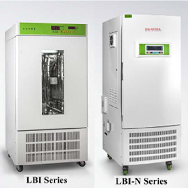
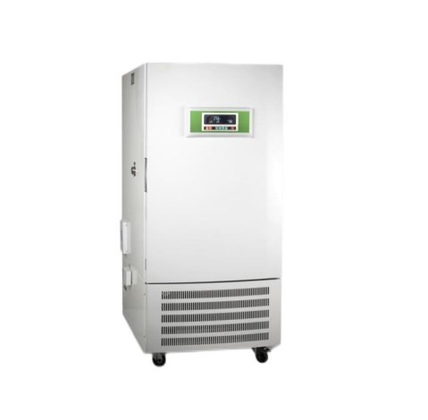
Biochemical incubators are invaluable pieces of laboratory equipment, serving vital roles in scientific research and education across various fields, including plant biology, microbiology, genetics, medicine, and environmental protection. These versatile devices are equipped with a two-way temperature adjustment system, enabling precise temperature control, a critical factor for successful experiments. Biochemical incubators find applications in biology, genetic engineering, medicine, environmental research, agriculture, and more. In this article, we’ll delve into the essential aspects of installing and maintaining a biochemical incubator.

Biochemical incubators

Installation of a Biochemical Incubator:

Power Supply:

Ensure that the biochemical incubator is connected to a reliable 220V/50Hz power supply. A grounded power supply circuit is essential for safe operation.

Location and Ventilation:

Place the biochemical incubator in a well-ventilated and dry room, away from direct sunlight. Maintain a minimum distance of 10 centimeters between the incubator and the wall to allow proper airflow.

Stability:

Adjust the base of the incubator using the bottom adjusting screw to ensure stable positioning.

Power On:

Turn on the power switch, setting it to the “on” position. The incubator will enter the powered-on state, allowing temperature and time settings.

Time Setting:

To set the time, press the temperature/time key once to activate the time setting indicator. Use the set key to enter the time setting mode, and adjust the time as needed using the ∧ and ∨ keys. Press the set key again to save the desired time setting.

Temperature Setting:

Press the temperature/time key once more to activate the temperature setting indicator. Similar to time setting, use the set key to enter the temperature setting mode, adjust the desired temperature using the ∧ and ∨ keys, and save the setting with the set key.

LBI-N Biochemical Incubator

Maintenance of the Biochemical Incubator:

Avoid Frequent Value Changes:

To prevent frequent compressor starts and potential overloads, refrain from frequently changing the set values during use.

Lighting Switch:

When lighting is unnecessary inside the incubator, switch off the lighting to maintain a stable upper-layer temperature and extend the lamp’s lifespan.

Transportation Precautions:

During transportation, never place the incubator upside down or at an angle greater than 45 degrees to avoid damage.

Fuse Check:

The incubator is equipped with two sets of fuses. In case of operational issues, disconnect the power, check the fuses’ condition, and then proceed with further troubleshooting if needed.

Power Off During Non-Use:

When not in use, keep the incubator dry and disconnect the power supply to conserve energy.

Axial Flow Fan Maintenance:

Regularly check the axial flow fan inside the incubator for proper operation to ensure uniform temperature distribution. Avoid overcrowding the incubator with items and ensure the fan’s air outlet remains unblocked during experiments.

Avoid Physical Contact:

Avoid physical contact with the temperature sensor inside the incubator, as it can disrupt temperature control.

Cleaning:

To maintain the incubator’s appearance, refrain from using corrosive solutions on its exterior. Use a dry cloth or alcohol to clean the interior, ensuring it remains free from contaminants.

In conclusion, the proper installation and maintenance of a biochemical incubator are crucial for ensuring accurate and consistent results in various scientific and research applications. By following these guidelines, researchers can maximize the functionality and lifespan of this essential laboratory equipment.

Automatic Refractometer: Everything You Need to Know

Refractive index measurement stands as a straightforward and precise technique for assessing the purity of organic compounds. In numerous binary systems, a definitive correlation exists between the refractive index and composition, making it a valuable parameter for composition analysis. The refractive index is a vital optical property of transparent materials, particularly when it falls within the range of 1.30 to 1.70. In this range, the total reflection method becomes advantageous due to its convenience, rapid operation, minimal environmental requirements, and the absence of a necessity for a monochromatic light source.

Automatic Refractometer

The refractometer, constructed using the total reflection method, serves as a specialized instrument for gauging the refractive index of transparent or translucent liquids. The utilization of an automatic refractometer to ascertain liquid composition is a prevalent technique in petrochemical, light industrial food, and other production and scientific research fields.

Functions of the Light Meter

Multilingual Interface and Data Output: Equipped with a full-color touch screen and a robust processor, the light meter offers menus in multiple languages. It facilitates data output via RS232, USB, and Bluetooth, enabling connections to computers, printers, and auxiliary devices like barcode readers.

Versatile Measurement Items: The LED touch screen allows users to switch between 16 different measurement parameters, including Refractive Index, Brix, Temperature Corrected Refractive Index, Temperature Corrected Brix, Zeiss, Butyric Acid, HFCS (42), HFCS (55), Urine Liquid SG, Osler, Baume, Babo, sodium chloride, and more (additional measurement items can be programmed as needed).

Temperature Control and Modes: The temperature-controlled refractometer offers four measurement modes: continuous mode (updated every 2 seconds), single scan mode (initiated after stabilization), automatic printing mode, and stable mode (based on user-defined fluctuation range for improved accuracy).

User-Friendly Data Input: Users can opt for keyboard or numeric keyboard input. When printing, the refractometer sends the instrument’s time, date, and serial code along with the print data to the printer.

Advanced Data Analysis: The refractometer allows users to set upper and lower alarm limits, calculate average values, read standard deviations, and view real-time data curves.

Automatic Refractometer Digipol R Series

Proper Usage of a Refractometer

Initial Calibration: Before commencing measurements, verify the readings using distilled water or a standard sample. To use a standard sample, apply 1-2 drops of bromonaphthalene to the polished prism surface and affix it to the refractive prism. Ensure that the reading field of view matches the value on the standard sample, and check if the boundary image aligns with the center of the reticle. If not, gently adjust the animal lens using a screwdriver until the image aligns correctly. This minimizes initial errors, including operator aiming errors.

Calibration and Consistency: Once calibrated, refrain from moving this part during subsequent measurements. Routine measurement typically does not require instrument recalibration. If any doubts arise about the refractive index indication, check for initial errors and correct them.

Regular Maintenance: Before each measurement and calibration, gently clean the rough surface of the incident prism, the polished surface of the refractive prism, the polished surface of the standard sample (1:1), and absorbent cotton with anhydrous ethanol mixture. This prevents the presence of contaminants that could affect imaging clarity and measurement precision.

Refractometer Maintenance

Storage: Store the instrument in a dry and well-ventilated room to prevent mold growth on optical components caused by humidity.

Cleaning: Promptly clean the instrument, including optical parts, metal components, and painted surfaces, when exposed to corrosive liquids. Always clean the instrument after use.

Sample Quality: Ensure that tested samples are free from hard impurities. When analyzing solid samples, take precautions to protect the refractive prism’s surface from roughness or indentation.

Cleanliness: Maintain the refractometer’s cleanliness by avoiding contact with greasy or sweaty hands. In case of dust on optical surfaces, gently wipe it with high-grade deerskin or long-fiber absorbent cotton, and blow it away using a gentle stream of air. For oil stains on optical components, promptly wipe them with alcohol.

Avoid Vibration: Prevent strong vibrations or shocks to the refractometer, as they can damage its components and compromise measurement accuracy.

How to Achieve Precise Tension Control in High-speed Web Processing Applications

In high-speed web processing applications like printing, coating, laminating, and converting, maintaining precise tension control is paramount. Tension, in this context, refers to the force applied to a continuous web of material as it undergoes various manufacturing phases. This article delves into the importance of tension control, the challenges it presents, and the methods and technologies utilized to achieve it in high-speed web processing applications.

tension control

Why Tension Control Matters in High-Speed Web Processing

Tension control in high-speed online processing is not just a technical detail; it’s a critical factor impacting product quality, resource efficiency, energy conservation, and overall operational effectiveness.

Ensuring Product Quality

Tension control plays a pivotal role in maintaining product quality. Consistent tension levels ensure uniform treatment of the web material, preventing defects like misaligned prints, distortion, smearing, or uneven coating distribution.

Reducing Waste

Precise tension control directly affects material utilization and waste reduction. High-speed processing often involves expensive materials, making it vital to prevent material breakdown due to over-tensioning or issues like wrinkling, misalignment, or tearing due to under-tensioning.

Enhancing Energy Efficiency

Proper tension control optimizes energy usage in high-speed web processing equipment. Over-tensioning can strain motors and drives, leading to increased energy consumption and maintenance costs. Maintaining constant tension contributes to cost savings and sustainability.

Boosting Process Efficiency

High-speed web processing requires synchronization among various components. Tension control acts as the linchpin, ensuring these components work efficiently together, reducing downtime, and enhancing overall process efficiency.

Reducing Defective Products

Tension control not only enhances product quality but also helps avoid the production of defective items, preventing financial losses and safeguarding a company’s reputation.

tension controller

Challenges of Tension Control in High-Speed Web Processing

Tension control in high-speed web processing faces numerous challenges due to the dynamic nature of these operations. Overcoming these obstacles is essential to maintaining product quality, reducing waste, and ensuring effective operation.

Variable Material Properties

Web materials exhibit variations in thickness, elasticity, and surface qualities, impacting tension control and requiring constant adjustments.

Speed Variations

High-speed processing involves rapid changes in web speed, which can introduce sudden tension fluctuations that must be managed for consistent product quality.

Web Accumulation and Splicing

Operations like web accumulation and splicing require precise tension control to prevent material and equipment damage during transitions.

Web Width Changes

Altering the width of the web can lead to tension fluctuations, necessitating real-time tension adjustments.

Web Flutter and Vibration

Dynamic forces like web flutter and vibration can be challenging to combat, requiring advanced control systems and responsive equipment.

Friction and Slip

Inconsistent friction and slip between the web and equipment components can affect tension control.

Complex Web Paths

Maintaining continuous tension in complex web paths with multiple rollers, guides, and direction changes can be difficult.

Load Variations

Variations in the amount of web material on a roll can impact tension and require adjustments.

Material Stretch and Shrinkage

Certain materials may stretch or shrink under tension, necessitating correction for precise control.

Temperature and Humidity Changes

Temperature and humidity variations can impact web material properties and cause tension differences.

Safety Considerations

Implementing safety mechanisms is essential to prevent over-tensioning, and safeguarding equipment and personnel.

T500 web tension controller

Key Methods for Tension Control

Various methods and technologies are employed to achieve precise tension control in high-speed web processing applications:

Dancer Systems

Load Cells

Pneumatic Brakes and Clutches

Closed-Loop Tension Control

Web Guiding Systems

Tension Control Software

Safety Mechanisms

The choice of tension control method depends on the specific requirements and challenges of the web processing application. In many cases, a combination of these strategies may be employed to achieve the necessary level of precision and responsiveness.

Conclusion

Tension control is indispensable in high-speed web processing applications, ensuring product quality, waste reduction, and process efficiency. Manufacturers can achieve precise and reliable tension control by integrating appropriate mechanical components, sensors, and control systems. As technology advances, the future of web tension control may bring even more sophisticated systems and automation, enhancing the potential of high-speed web processing across various industries, from printing to packaging and beyond.

What are Well Logging Simulators in Energy Industry: Characteristics and Substantial Impacts

The significance of well logging, a technique used to measure and record properties of rocks and fluids in a wellbore, is on the rise within the energy industry. Well logging simulators have revolutionized this process by providing virtual platforms for simulating and analyzing downhole measurements. In this article, we will explore well logging simulators, their characteristics, and their substantial impact on the energy industry.

Open Hole Well Logging Simulator

Understanding Well Logging Simulators

Well logging simulators are advanced computer models that replicate the behavior of downhole measurements and the underlying subsurface formations. These simulators employ intricate algorithms rooted in physics, geology, and engineering principles to simulate and predict logging responses. They enable energy companies to execute virtual well logging exercises, assess alternative logging equipment and techniques, and gain valuable insights into reservoir characteristics by generating a digital representation of the wellbore and the surrounding formation.

Modeling Logging Tools

Simulators precisely model the physics and measurements of various logging tools, including gamma-ray, resistivity, neutron porosity, and sonic tools. These models account for factors like tool shape, sensor response, and interactions with the formation, allowing engineers to replicate the behavior of specific logging tools and assess their performance in diverse geological contexts.

Formation Modeling

Well logging simulators include accurate simulations of subsurface formations, encompassing aspects such as rock types, lithology, porosity, and fluid saturation. These models incorporate complex geological variations, enabling engineers to simulate various scenarios, comprehend formation characteristics, and evaluate their impact on logging responses. Companies can make informed decisions regarding reservoir properties and optimize resource extraction strategies by analyzing these simulated measurements.

Calibration and Validation

Simulators facilitate the calibration and validation of logging responses by comparing simulated results with real field data. This process ensures that the simulation models faithfully represent downhole measurements and offer reliable insights into reservoir properties. Through validation, companies can build confidence in the accuracy of the simulators and effectively utilize them for data interpretation and reservoir characterization.

Scenario Analysis

Engineers can utilize well logging simulators for scenario analysis, simulating different logging scenarios under varying conditions. By modifying logging tool parameters, wellbore conditions, or reservoir characteristics, companies can assess the impact of various variables on logging responses. This approach aids in optimizing logging procedures, identifying formation characteristics, and reducing uncertainty in reservoir evaluation.

Production Well Logging Simulator

The Profound Impact of Well Logging Simulators on the Energy Industry

Cost Optimization

Well logging simulators help organizations optimize their logging strategies and reduce field operation costs. By conducting virtual well logging exercises, companies can evaluate different logging equipment and methodologies, identify the most efficient ones, and optimize the deployment of actual logging tools in the field. This minimizes the need for additional trips and reduces the risk of failed logging runs, resulting in substantial cost savings.

Enhanced Data Interpretation

Engineers can use well logging simulators to assess logging results and extract relevant information about reservoir features. By simulating various scenarios and analyzing the simulated observations, companies can enhance their understanding of formation parameters such as porosity, permeability, and fluid saturation. This improved data interpretation leads to more accurate reservoir modeling, resource assessment, and decision-making.

Improved Reservoir Characterization

Well logging simulators play a crucial role in reservoir characterization, providing precise information about subsurface formations. Engineers can assess formation attributes, analyze reservoir heterogeneity, and identify potential production zones by modeling logging responses. This data is essential for optimizing well placement, developing completion procedures, and maximizing hydrocarbon recovery from reservoirs.

Risk Mitigation

Well logging simulators aid in mitigating risks associated with reservoir appraisal and resource extraction. Companies can assess uncertainties and hazards related to various logging scenarios by modeling logging responses. This enables them to identify potential issues, formulate suitable contingency plans, and reduce overall risk in reservoir development and production activities.

Training and Skill Development

Well logging simulators serve as valuable training and skill development platforms for industry personnel. They offer a safe and controlled environment for engineers to practice and enhance their logging interpretation skills, especially as the complexity of logging tools and procedures increases. This results in a more knowledgeable workforce and enables the effective use of logging data for reservoir evaluation.

In Summary

Well logging simulators are instrumental in uncovering subsurface information and ensuring effective resource extraction within the energy industry. They can provide precise reservoir characterization, efficient well logging strategies, and improved decision-making by offering virtual platforms to replicate logging responses.

A Step-by-Step Animation Guide to Diesel Engine Assembly and Disassembly

Diesel engines are renowned for their efficiency and durability, finding applications in a wide array of machinery, from automobiles to heavy industrial equipment. Whether you’re a seasoned technician or an eager enthusiast, understanding the intricate process of assembling and disassembling a diesel engine is paramount for maintenance and repair. In this article, we present a comprehensive step-by-step guide that takes you through the animation of intricate procedure for both diesel engine assembly and disassembly.

Animation of Diesel Engine Assembly and Disassembly

Step-by-Step Animation of Diesel Engine Disassembly

Engine disassembly is a pivotal phase in the maintenance, repair, or reconstruction of a diesel engine. Our step-by-step animation provides a clear and detailed method for dismantling various engine components:

Step 1: External Component Removal

The animation initiates with the removal of external components such as the air filter, fuel lines, and exhaust system. These parts are systematically disconnected and detached from the engine, creating unobstructed access to the internal components.

Step 2: Cylinder Head Removal

Following the external component removal, the animation proceeds to demonstrate the meticulous removal of the cylinder head. This intricate process involves the careful disconnection of the intake and exhaust manifolds, the valve train components, and the head bolts. Once these steps are completed, the cylinder head can be gently lifted off the engine block.

Step 3: Piston and Connecting Rod Removal

To access the pistons and connecting rods, the animation expertly guides you through each step of the removal process. This includes the removal of piston rings, the disconnection of connecting rod caps, and the safe extraction of the piston and connecting rod assemblies from the engine block.

Step 4: Crankshaft and Main Bearing Removal

The animation then focuses on the crankshaft, a critical component responsible for translating the piston’s up-and-down motion into a rotating motion. Here, you’ll witness the removal of the main bearing caps, allowing for the careful extraction of the crankshaft from the engine block.

Step 5: Camshaft and Timing Gear Removal

In the final phase of engine disassembly, the animation tackles the removal of the camshaft and timing gears. These vital components play a pivotal role in regulating the engine’s valve openings and closings and ensuring precise timing. The animation meticulously demonstrates the separation of the camshaft, removal of the timing gears, and disengagement of the timing chain or belt.

By following these step-by-step instructions, technicians and enthusiasts alike can proficiently disassemble an engine, inspect its internal components, and perform necessary repairs or replacements.

Animation of Diesel Engine Assembly and Disassembly

Step-by-Step Animation of Diesel Engine Assembly

Engine assembly is a precise and intricate procedure that involves methodically piecing together various components to create a fully operational engine. Our animation walks you through this assembly process step by step:

Step 1: Camshaft and Timing Gear Installation

The animation commences with the installation of the camshaft, timing gears, and timing chain or belt. Precise alignment and synchronization are crucial for optimal engine performance. You’ll witness the correct placement and installation of the camshaft and timing gear assembly.

Step 2: Crankshaft and Main Bearing Installation

Next, the animation guides you through the installation of the crankshaft and main bearings. The crankshaft is meticulously positioned and aligned within the engine block, with the main bearing caps tightened in the proper sequence and to the recommended torque specification. This step ensures smooth rotation of the crankshaft and proper support.

Step 3: Piston and Connecting Rod Installation

The animation then focuses on the installation of pistons and connecting rods. This involves precise positioning of piston rings on the pistons and secure attachment of connecting rods to the crankshaft. You’ll witness how these components should be oriented and assembled to ensure efficient combustion and power delivery.

Step 4: Cylinder Head Installation

The animation illustrates the installation of the cylinder head in this step. Proper positioning of the cylinder head onto the engine block, along with the installation of new head gaskets, is crucial to create a tight seal. The animation emphasizes the correct torquing sequence and values for the head bolts to achieve the necessary clamping force.

Step 5: Reassembly of External Components

In the final phase of engine assembly, the animation demonstrates the reconnection and secure attachment of external components, including the air filter, fuel lines, and exhaust system. These components are essential for the engine’s proper functioning and optimal performance.

In summary, understanding the intricate processes is paramount for effective maintenance and repair of diesel engines. This article’s step-by-step animation guide of diesel engine assembly and disassembly provides a visually informative explanation of these complex procedures, empowering technicians and enthusiasts to navigate the intricacies involved. By following these methods, you can ensure the reliability and longevity of your diesel engine.

Surface Phosphating Treatment: Purposes and Factors Influencing Effectiveness

In the realm of fastener surface treatment processes, several methods, including electroplating, electrophoresis, painting, oxidation blackening, and phosphating, are commonly employed. This article will focus on surface phosphating treatment, shedding light on its purpose, key factors influencing its effectiveness, and the advantages it offers.

What is Surface Phosphating Treatment?

Surface phosphating treatment is a chemical and electrochemical process that generates a phosphate chemical conversion film on metal surfaces. This film is referred to as a phosphating film and is primarily used on iron and steel surfaces, although it can also be applied to non-ferrous metals like aluminum and zinc.

surface phosphating treatment screw

Purposes of Surface Phosphating Treatment:

Enhancing Paint Adhesion and Corrosion Resistance: Phosphating treatment acts as a primer before painting, improving the adhesion and corrosion resistance of the paint layer. The porous nature of the phosphating film allows paint to penetrate into its structure, creating a strong bond with the metal surface.

Protecting Base Metal: It provides a protective layer on the base metal, reducing susceptibility to corrosion. The phosphating film serves as a non-metallic, non-conductive isolation layer, preventing the formation of micro-batteries on the metal’s surface and effectively safeguarding the underlying metal from corrosion.

Anti-Friction Lubrication: Surface phosphating treatment can function as a lubricant in metal cold working processes, reducing friction and wear.

Creating a Clean Surface: Phosphating film only forms on clean, oil-free, and rust-free metal surfaces. Consequently, metal workpieces subjected to phosphating treatment exhibit a clean, grease-free, and rust-free surface.

Factors Influencing Phosphating Effectiveness:

Temperature: The temperature plays a significant role in the phosphating process. Lower temperatures result in thinner phosphating layers with finer crystallization, while higher temperatures lead to thicker layers with coarser crystallization.

Free Acidity: The concentration of free hydrogen ions in the phosphating solution, known as free acidity, affects the process. Excessive free acidity accelerates corrosion on steel surfaces, hindering phosphating film formation and reducing corrosion resistance. Conversely, low free acidity results in slow corrosion reactions and difficulties in film formation.

Total Acidity: Total acidity, the sum of phosphates, nitrates, and acids in the solution, should ideally be controlled within the specified range. Maintaining higher total acidity accelerates phosphating reactions and produces finer and more uniform film grains.

pH Value: The pH value of the solution is crucial. Manganese phosphating solutions are typically kept between pH 2-3 to prevent powder formation on the workpiece surface. For iron systems, the pH is generally controlled between 3-5.5.

Ion Concentration: The concentration of ions in the solution, such as Fe2+ and Zn2+, also affects phosphating outcomes. Excessive Fe2+ can hinder film formation and reduce corrosion resistance, while high levels of Zn2+ result in coarse-grained films and increased brittleness.

In conclusion, surface phosphating treatment is a valuable process with multiple benefits, including improved paint adhesion, corrosion protection, lubrication, and surface cleanliness. To achieve optimal results, it is essential to consider and control factors such as temperature, acidity levels, total acidity, pH value, and ion concentration during the surface treatment process.

What are Springs: Functions, Manufacturing Process and Causes of Failure

Springs are mechanical components that harness elasticity to perform various functions. They are widely employed in both the mechanical and electronics industries, offering a versatile means of converting mechanical energy into deformation energy and vice versa. Springs exhibit the remarkable property of elastic deformation when subjected to loads, reverting to their original state upon unloading. The stiffness of a spring, often referred to as its spring constant, is determined by the ratio of the load applied to the resulting deformation. Higher stiffness indicates a firmer spring.

custom spring

Functions of Springs

Springs serve a multitude of functions in various applications:

Cushioning and Damping: Damping springs beneath vehicles and trains, as well as buffer springs in different types of buffers, absorb and dissipate energy to provide a smooth and controlled motion.

Mechanism Control: Springs like valve springs in internal combustion engines and clutch control springs play a pivotal role in regulating the movement of mechanical systems.

Energy Storage and Release: Devices such as clock springs and gun latch springs are designed to store energy and release it as needed.

Force Measurement: Springs are utilized in force measurement instruments like spring scales and dynamometers.

Manufacturing of Springs

The manufacturing process of springs involves several key steps:

Rolling: Large-scale production often employs universal automatic roll spring machines for rolling.

Hook Fabrication: For small-scale or custom production, springs can be made on general lathes or crafted by hand.

Fine Finishing: Precision finishing is essential to ensure the spring meets the required specifications.

Heat Treatment: The spring undergoes heat treatment, typically including quenching and medium-temperature tempering.

Performance Testing: Quality control involves rigorous testing of the spring’s surface, ensuring it is free from defects such as scars and decarburization.

For springs with wire diameters less than or equal to 8mm, the cold coiling method is commonly used. When the diameter exceeds 8mm, the hot coiling method is adopted, with the coils heated to temperatures ranging from 800°C to 1000°C.

tension spring

Causes of Spring Failure

Understanding the factors that can lead to spring failure is essential:

Plastic Deformation: When external loads exceed the material’s yield strength, permanent plastic deformation can occur, preventing the spring from returning to its original shape and size.

Fatigue Fracture: Repeated alternating stress can lead to the development of surface defects and fatigue-induced cracks.

Rapid Brittle Fracture: Material or processing defects, heat treatment issues, or high-impact loads can result in sudden brittle fractures.

Corrosive Medium: Springs used in corrosive environments may experience stress corrosion cracking, while high-temperature applications can lead to creep and stress relaxation, causing permanent deformation.

Precautions for Springs

In practical applications, compression springs should maintain their working length even when subjected to forces beyond the material’s elastic limit. To ensure this, the finished spring’s length should equal the calculated length of the spring plus the initial compression volume. Additionally, during heat treatment, especially for springs requiring quenching and tempering, care should be taken to prevent spring shortening due to its weight.

Spring Deformation Applications: Spring Collets

One notable deformation application of springs is the spring collet, also known as a spring sleeve. Spring collets offer rapid and highly accurate positioning, facilitating the secure clamping of workpieces. Their advantages include:

Small Diameter Compatibility: Ideal for processing small-diameter workpieces.

Fast Loading and Unloading: Enables swift workpiece changes.

Short Replacement Times: Allows quick swapping of fixtures of varying sizes.

High Clamping Accuracy: Offers precision exceeding that of chucks.

Cost Efficiency: Reduces costs and enhances flexibility compared to chucks.

Enhanced Processing: Ideal for machine tools with internal interpolation spindle structures, providing greater processing space and rigidity.

Surface Protection: Safeguards workpiece surfaces and delivers superior cutting torque.

In conclusion, springs are indispensable components across various industries, performing an array of vital functions. Understanding their applications, manufacturing processes, and considerations ensures their effective utilization in mechanical and electronic systems. The spring collet, a deformation application, exemplifies how springs can offer high precision and versatility in specific applications.

What are the Key Factors for Choosing the Right Biochemical Incubators

Biochemical incubators are a common sight in laboratories and among environmental protection operators, but for those in the role of purchasers, these machines may seem somewhat unfamiliar. However, choosing the right biochemical incubator is crucial to ensure efficient operations and reliable results. When making a purchase, buyers often engage in thorough research and consultations with biochemical incubator manufacturers. This diligence stems from the fact that the prices of biochemical incubators can vary significantly, with higher quality models naturally commanding a premium. If the price difference isn’t substantial, the craftsmanship of the incubator may not differ greatly. To make a cost-effective and high-quality purchase, consider the following key factors:

LBI-N Biochemical Incubator

1. Compressor Type:

The compressor plays a central role in the biochemical incubator, as it controls the refrigeration temperature. Currently, the two most common types of compressors in the market are fluorine-free and fluorine-containing. Increasingly, mainstream biochemical incubators are adopting fluorine-free refrigeration.

Fluorine-free compressors typically use R134a refrigerant, which is environmentally friendly, as it does not harm the ozone layer, has no greenhouse effect, and offers energy-saving and efficient cooling. These compressors have a high latent heat of evaporation, strong cooling capacity, low power consumption, and compatibility with various compressor lubricants.

Fluorine compressors, on the other hand, rely on freon as a refrigerant, which can contribute to ozone layer depletion. Given the importance of the ozone layer in protecting against harmful ultraviolet rays, finding alternatives to fluorine is essential.

While the principles of both compressor types are the same, the refrigerants they use differ significantly, leading to varying costs and, consequently, different prices for biochemical incubators.

2. Temperature Control Range:

Select a biochemical incubator with a temperature control range that suits your experimental requirements. Options typically range from room temperature +5°C to 60°C, 0-60°C, 4-60°C, and 5-50°C. Standard biochemical incubators usually maintain a constant temperature between 5-50°C, while low-temperature biochemical incubators can achieve temperatures as low as -10°C.

Biochemical incubators

3. Incubator Volume:

Biochemical incubators are available in various volumes, including 80L, 150L, 200L, 250L, 300L, and 400L. Choose a size that aligns with your laboratory’s needs.

4. Refrigerant Choice:

In today’s environmentally conscious world, opting for a biochemical incubator that uses a fluorine-free refrigerant is advisable, considering its positive impact on environmental protection.

5. Power Consumption:

Consider the power rating of the biochemical incubator, as it directly affects electricity consumption. Lower power consumption can lead to cost savings, especially with the rising cost of electricity.

6. Dimensions:

Evaluate the incubator’s dimensions, including its internal and external measurements and packaging size. Ensure your laboratory can accommodate the incubator, and that the internal dimensions are suitable for your specific experiments. If you require a large incubator, confirm that your laboratory’s door dimensions can accommodate it.

7. Temperature Control Accuracy:

Examine parameters such as temperature fluctuation, resolution, and uniformity to ensure they meet your experimental requirements.

8. Technical Guidance and After-Sales Support:

If you lack experience with biochemical incubators, consider whether the manufacturer offers technical guidance from engineers to help you use the equipment proficiently. After-sales service is crucial due to the high cost, size, and weight of these machines, as transportation and maintenance can pose challenges. Verify the warranty terms and the availability of on-site technical support and services.

By carefully considering these key factors for choosing the right biochemical incubators, purchasers can acquire the product which meets their laboratory’s needs effectively.

What is Gas Chromatography: Outstanding Benefits and General Procedure

Gas chromatography, a powerful analytical technique, employs gas as a mobile phase within a chromatographic column. This core component of gas chromatography significantly influences the overall performance of the technique. Chromatographic columns come in two main types: packed columns and capillary columns.

GC1290 Gas Chromatography

Packed columns are filled with solid adsorbents or carriers containing fixed liquids. They are versatile, capable of separating compounds with high boiling points like nitrogen, oxygen, hydrogen, and argon. On the other hand, capillary columns offer high separation efficiency by coating the inner wall with a stationary phase liquid. This phase can be solid or liquid, each with distinct adsorption capacities for various components. Examples of weak adsorbents include sucrose, starch, inulin, talc, and potassium carbonate.

Gas chromatography boasts several outstanding advantages:

High Separation Efficiency: It can effectively separate complex mixtures of compounds with closely matched physical and chemical properties. This enables both qualitative and quantitative analyses, sometimes resolving tens or even hundreds of components simultaneously in a single analysis.

High Sensitivity: Gas chromatography can detect impurities at the ppm or even ppb level. Only minute gas or liquid samples, often less than 1 mL, are required for analysis.

Rapid Analysis: With the aid of computers, precise results can be obtained in seconds, making it a swift analytical method.

Wide Range of Applications: Gas chromatography is versatile, capable of analyzing gaseous, volatile liquid, and solid samples. It finds extensive use in organic analysis, covering approximately 20% of organic compounds, and can even analyze some inorganic substances following appropriate transformations.

The General Procedure for Gas Chromatography:

General procedure for a gas chromatography

The sequence of peak times serves as the basis for qualitative analysis, while peak area or peak height is used for quantitative analysis.

Three Components of Industrial Gas Chromatography:

Industrial gas chromatography, compared to its laboratory counterpart, incorporates a sampling system, utilizes column-cutting technology, and employs complete automation for program control and information processing.

1. Sampling System:

The sampling system handles sample collection and pretreatment, serving as the interface between the production process and industrial gas chromatography. Initial sample pretreatment steps, such as decompression, water removal, and dust removal, occur external to the chromatography system.

Internally, the gas chromatography system features functionalities such as pressure regulation, flow path switching, flow monitoring, atmospheric balance, and calibration with standard gas or liquid. Design considerations encompass corrosion resistance of system components, leak prevention, explosion protection, reduction of transfer lag time, and control of contamination from evacuation.

2. Carrier Gas Flow System:

The carrier gas flow system comprises a source of carrier gas, purifiers, pressure and flow stabilization, and adjustment devices. Typically, high-pressure gas stored in cylinders serves as the carrier gas source, with a pressure-reducing valve reducing it to 0.1-0.5 MPa. High purity and stability are prerequisites for the carrier gas, necessitating the use of materials like silica gel, molecular sieve, and activated carbon to adsorb moisture and hydrocarbon compounds.

Carrier gases such as hydrogen, nitrogen, and argon may be employed. Maintaining constant gas flow with minimal variation (<1%) is crucial, necessitating the inclusion of flow meters, regulating valves, and pressure-stabilizing valves in the gas path.

3. Sampling Device:

Sampling involves the quantitative introduction of a gas, liquid, or transformed solid sample into the chromatographic column for separation. Consistency in injection quantity, injection duration, and sample vaporization rate significantly impacts the repeatability and accuracy of quantitative results.

(1). Gasification Chamber:

The gasification chamber features a metal block exterior with a controllable operating temperature ranging from 50-500°C. Temperatures exceeding 250°C utilize inner glass tube structures to prevent unwanted catalytic effects. The gasification chamber’s primary function is to ensure instantaneous vaporization of liquid samples. It requires preheating of the carrier gas before entry, while the silicone rubber pad should remain cool to prevent unintended chemical reactions.

Injection valve using gas chromatography

(2). Injection Valve:

Sampling valves must exhibit excellent airtightness, minimal dead volume, reliability, durability, and rapid switching times. In specific applications, resistance to corrosion and operation within defined temperature ranges may also be necessary.

An Extensive Comparison of Various Web Guiding Systems: Which One to Choose

Web guiding systems have revolutionized the manufacturing industry, particularly in processes involving continuous web materials, by offering precise alignment and tension control. As production demands continue to rise, the choice of the right web guide system becomes increasingly critical. This article presents an extensive comparison of various web guiding systems, highlighting their operational principles, advantages, and ideal applications.

automatic web guiding system

Line Edge Sensor-Based Web Guiding Systems

At the core of these web guide systems are web line edge sensors that detect changes in light, infrared, or sound patterns as web materials pass through their field of view. These sensors receive signals that reflect the alignment status of the web by emitting beams of light, infrared radiation, or ultrasonic waves across it. When the web deviates from its intended path, the sensor’s signal pattern shifts, prompting the web guiding system to make precise adjustments, realigning the web to the centerline or ideal alignment. This real-time feedback loop ensures the web materials remain consistently aligned throughout the production process.

Benefits

Real-Time Alignment: Line edge sensors provide rapid feedback, facilitating quick adjustments and minimizing misalignment.

Non-Contact Detection: These sensors offer non-contact sensing, safeguarding fragile materials.

Versatility: Line edge sensors are compatible with a wide range of materials, making them suitable for various industries.

Ideal Applications

Printing: Ensuring accurate alignment of paper or labels during printing processes.

Packaging: Precise alignment of packaging materials for uniform packing quality.

Textiles: Maintaining fabric alignment for flawless weaving or printing.

Labeling: Accurate label alignment on products or packaging materials.

Converting: Ensuring precision in cutting, slitting, and perforation during manufacturing operations.

web guide system

Tension Sensor-Based Web Guiding Systems

Web guiding systems equipped with tension sensors are designed to monitor and manage the tension forces applied to moving web materials. These sensors detect variations in tension and provide real-time feedback, enabling swift adjustments to maintain optimal tension.

Benefits

Uniform Tension: Tension sensor-based systems ensure uniform tension across the web material, preventing flaws like creases and stretching.

Versatility: Different sensor types cater to different material types and industrial processes.

Real-Time Feedback: Immediate adjustments guarantee proper tension, enhancing product quality.

Ideal Applications

Textile Weaving: Maintaining consistent tension for seamless fabric weaving.

Paper Manufacturing: Precise tension control during plastic film extrusion and lamination.

Film Production: Accurate tension control for plastic film extrusion and laminating.

Labeling and Packaging: Tension control during label application and packing material production.

Capacitive Sensor-Based Web Guiding Systems

Capacitive sensor-based web guiding systems rely on sensing changes in capacitance induced by the presence of web materials. These sensors excel in detecting the position and alignment of non-conductive or low-conductive materials, which can be challenging for other sensor types.

Benefits

Alignment for Non-Conductive Materials: Capacitive sensors are effective in aligning materials with low conductivity, a task that can be problematic for other sensor types.

Consistent Detection: These sensors offer reliable alignment detection irrespective of material characteristics.

Precision Alignment: High precision ensures superior product quality.

Ideal Applications

Plastic Film Processing: Ensuring precise alignment during plastic film extrusion and laminating.

Labeling and Packaging: Aligning labels on non-conductive packaging materials.

Paper Manufacturing: Accurate alignment of non-conductive paper during printing and processing.

Textile Production: Maintaining alignment of non-conductive materials during weaving and printing.

Summary

Choosing the right web guide system demands a comprehensive understanding of each technology’s intricacies and its suitability for specific applications. Line edge sensor-based systems excel in swiftly aligning diverse materials, while capacitive systems thrive in aligning non-conductive materials. Tension sensor-based web guide systems are indispensable for ensuring consistency, while laser sensor-based systems offer unparalleled precision.

web guide machine work

When selecting web guide systems, manufacturers must consider factors such as material properties, production environment, required precision, and budget constraints. Each system type presents its own set of advantages and limitations, enabling manufacturers to tailor their choice to their unique production needs. In a world where precision and efficiency are paramount, the ability to choose the appropriate web guiding system represents a crucial step in enhancing product quality, minimizing waste, and maintaining competitiveness in today’s dynamic manufacturing landscape.

通过 WordPress.com 设计一个这样的站点
从这里开始