Drilling operations in the petroleum industry are inherently risky, demanding extensive training and preparation to ensure staff safety and optimize operational efficiency. In this context, innovative training tools play a crucial role. One such innovation is the portable drilling well control simulator, designed to provide realistic, hands-on training experiences in a compact and portable format.
Simulating Realistic Well Control Scenarios:
Well control is paramount in drilling operations, where the stakes are high. The drilling teams must receive realistic and effective training to ensure worker safety and equipment integrity. Simulators that faithfully recreate well-control scenarios are indispensable in this regard.
Trainees benefit from hands-on experience in addressing critical situations by simulating realistic well control scenarios. These simulators replicate the complexities and challenges encountered during drilling operations, enabling learners to develop essential skills, knowledge, and confidence to effectively manage emergencies. Let’s delve into how these simulators achieve such realistic simulations.
1. Dynamic Physics and Fluid Modeling:
Well control simulators employ intricate physics and fluid modeling methods to simulate the behavior of fluids encountered during drilling. They accurately represent the dynamic interactions between drilling mud, formation pressures, and wellbore conditions. By faithfully simulating fluid dynamics, these simulators can precisely replicate pressure fluctuations, influxes, and outflows that occur during well control incidents.
2. Real-Time Monitoring and Feedback:
Simulators provide real-time monitoring of critical parameters, including wellbore pressure, flow rates, and choke settings. Trainees can continuously monitor and analyze changing well conditions, allowing them to make informed decisions based on simulated data. Instant feedback enables trainees to assess the effectiveness of their actions and make real-time adjustments.
3. Emergency Scenarios:
Well control simulators offer a range of emergency scenarios to challenge trainees’ abilities. From well kicks and blowouts to loss of circulation, these severe conditions demand prompt and effective action. By simulating these emergencies, trainees can practice essential well control techniques, such as shutting down the well, managing pressure, and executing situation-specific well control procedures.
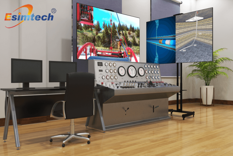
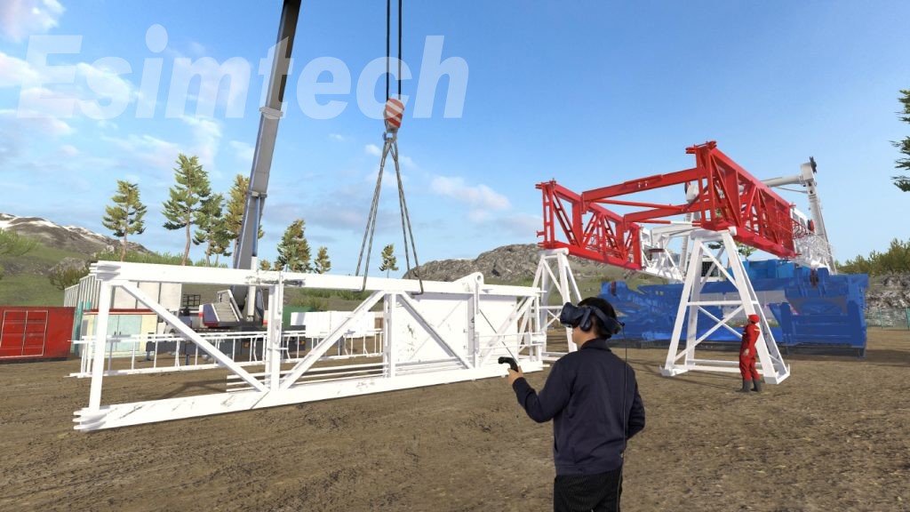
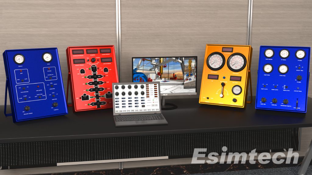
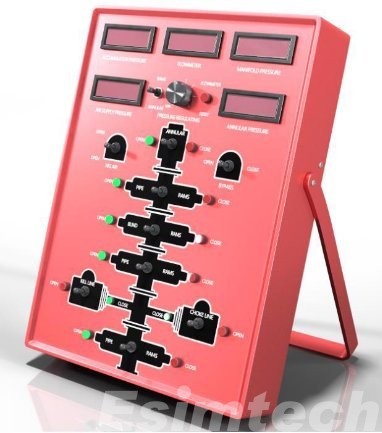
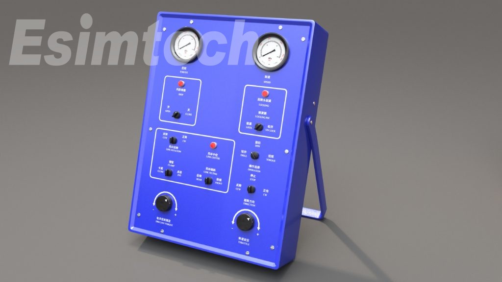
4. Equipment and Control Panel Replication:
To create a lifelike training environment, simulators replicate drilling rig equipment and control panels. Trainees can interact with virtual control panels and operate drilling equipment, including Blowout Preventers (BOPs), mud pumps, and chokes. This hands-on training enhances trainees’ familiarity with the equipment, improving their ability to respond swiftly and efficiently during well control incidents.
5. Communication and Decision-Making:
Well control simulators simulate the communication network and dynamics within a drilling team. Trainees practice coordinating actions with team members, sharing critical information, and managing resources effectively. This collaborative environment fosters teamwork and prepares trainees for the coordination required in real-world well control situations.
6. Variable Training Difficulty:
Simulators offer the flexibility to tailor the difficulty level of training scenarios to match the experience and skill levels of trainees. Novice drillers can start with basic scenarios and progress to more complex and challenging ones as their proficiency grows. This adaptive training approach ensures that students are adequately prepared for a wide range of well control scenarios encountered in the field.
Key Features and Benefits of Portable Drilling Well Control Simulators:
1. Hands-on Training:
The simulator provides a hands-on learning experience for well control techniques. Trainees actively engage with simulated equipment, control panels, and well control processes, gaining practical experience in handling crises and making critical decisions. This interactive approach enhances skill development and boosts trainees’ confidence.
2. Portability and Flexibility:
The portable nature of the simulator allows it to be easily transported and set up in various locations, including training centers, on-site training facilities, or even offshore platforms. This flexibility ensures convenient access to well control training, eliminating the need for trainees to travel long distances for training purposes.
3. Risk-free Environment:
The simulator creates a risk-free training environment where learners can practice and refine their well control skills without endangering crew safety or risking damage to equipment. It allows trainees to experiment with different strategies and techniques, enabling them to learn from failures and develop effective responses to well control challenges.
4. Performance Evaluation and Feedback:
The simulator tracks trainees’ progress and provides instant feedback on their actions and decisions. This evaluation approach empowers trainees to assess their performance, identify areas for improvement, and fine-tune their well control techniques. Continuous feedback and performance metrics enable focused training interventions and allow for monitoring progress over time.
5. Cost-Effective Training:
Investing in a portable drilling well control simulator can lead to long-term cost savings in training. Companies can reduce expenses related to travel, accommodation, and equipment rental by providing on-site or nearby well control training. The durability and reusability of the simulator contribute to sustained cost efficiency.
6. Enhancing Safety Awareness:
By simulating well control scenarios, the simulator enhances safety awareness among trainees. It allows them to experience potential risks and consequences associated with well control incidents firsthand, instilling a profound understanding of the significance of safety protocols and the importance of proactive risk management.
7. Team Collaboration and Communication:
The simulator promotes effective communication and teamwork among drillers and well control teams. In a virtual setting, trainees can practice coordinating actions, sharing information, and making group decisions. This fosters teamwork, enhances coordination skills, and improves the overall effectiveness of well control operations.
8. Scenario Customization:
The simulator offers the flexibility to tailor training scenarios to specific learning objectives. This customization allows trainees to gain firsthand experience with potential hazards and consequences of well control incidents, reinforcing the importance of safety precautions and proactive risk management.
9. Continuous Training and Skill Development:
The simulator supports ongoing training and skill development. It can be used to offer increasingly complex scenarios and challenges as trainees progress and master fundamental well control procedures. This incremental training approach ensures continuous skill growth and prepares learners for a wide range of real-world well control situations.
Conclusion:
The portable drilling well control simulator represents a significant advancement in safety and efficiency within the petroleum industry. It serves as a vital tool in training the next generation of competent drilling professionals as the industry continues to prioritize safety and enhance operational efficiency. With its realistic simulations, hands-on training, and numerous benefits, this innovative training tool contributes to safer and more efficient drilling operations.